
Moving bed coal pyrolysis based polygeneration device and method

A moving bed, coal pyrolysis technology, applied in combustion methods, direct heating and dry distillation, lighting and heating equipment, etc., can solve the problems of high equipment investment and operation cost, complex process, high investment cost, improve coal utilization efficiency, The effect of flexible system operation and high calorific value of gas

Inactive Publication Date: 2015-11-25
HUANENG CLEAN ENERGY RES INST
View PDF6 Cites 3 Cited by
  • Summary
  • Abstract
  • Description
  • Claims
  • Application Information

AI Technical Summary

Problems solved by technology

[0007] Among them, the main feature of technology (1) is the complete coal gasification technology as the core, and a variety of technologies are organically combined; in the system, pollutants can be effectively controlled, and the waste gas generated can be high-purity CO 2 , direct utilization or treatment; the use of advanced biological and chemical treatment methods can achieve near-zero discharge of pollutants, but the system is complex and the investment cost is high; technology (2) is to partially gasify coal in the reactor Coal gas is produced, and the semi-coke that has not been gasified is sent to the combustion furnace for combustion and utilization to generate steam for heating and power generation, and the forced conversion of fixed carbon by means of water vapor is no longer adopted.
Relative technology (1) This technology is relatively simple, but there are still disadvantages such as complex process and high equipment investment and operation costs

Method used


Image

  • Moving bed coal pyrolysis based polygeneration device and method
  • Moving bed coal pyrolysis based polygeneration device and method

Examples


Embodiment Construction

[0018] The present invention will be further described in detail below in conjunction with the accompanying drawings and specific embodiments.

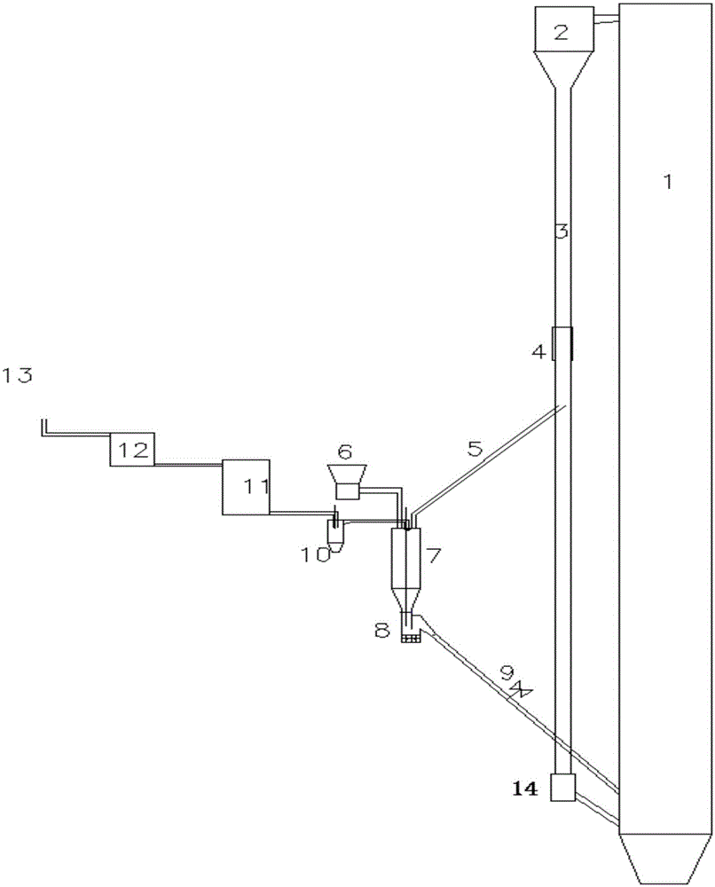
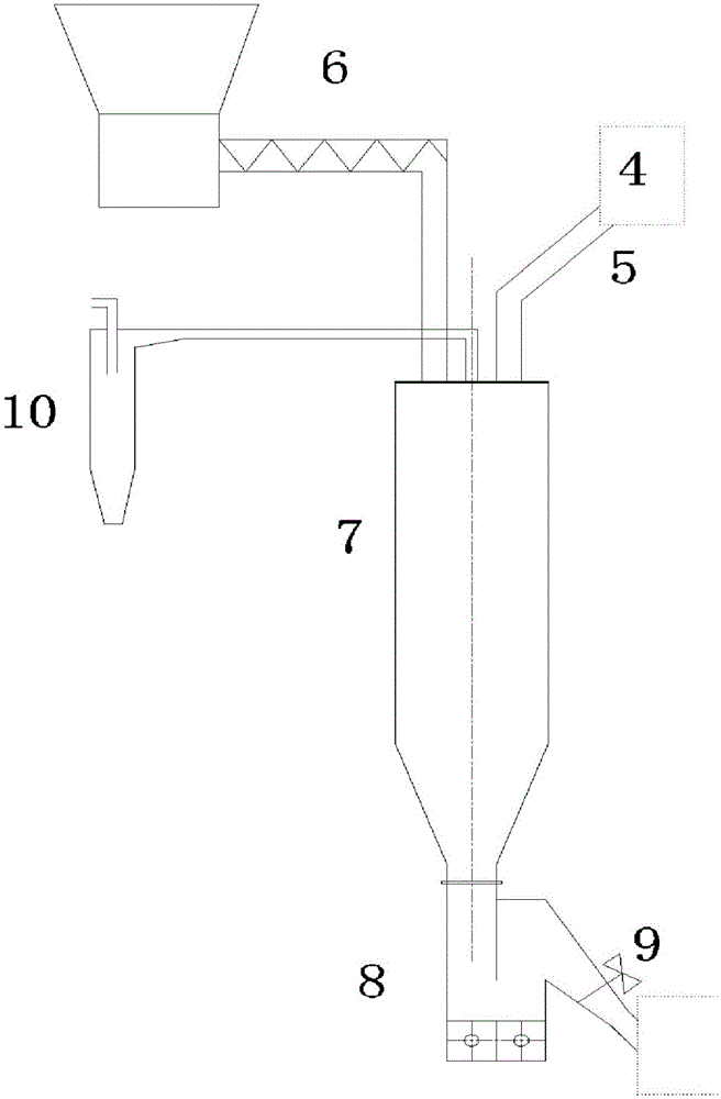
[0019] Such as figure 1 As shown, a moving bed coal pyrolysis polygeneration device of the present invention includes a circulating fluidized bed boiler furnace 1, a boiler separator 2 is connected to the top of the circulating fluidized bed boiler furnace 1, and a boiler separator 2 is connected to the bottom of the boiler separator 2. Standpipe 3, the bottom of the standpipe 3 communicates with the bottom of the circulating fluidized bed boiler furnace 1 through the boiler feeder 14, the middle part of the standpipe 3 is provided with a hot ash splitting device 4, and the hot ash splitting device 4 The top of the moving bed pyrolysis reactor 7 is communicated with the top of the moving bed pyrolysis reactor 7 through the moving bed hot ash flow pipe 5, and the top of the moving bed pyrolysis reactor 7 is also connected with the movi...


PUM


Abstract

The invention provides a moving bed coal pyrolysis based polygeneration device and method. The device comprises a circulating fluidized bed (CFB) boiler furnace, wherein the top of the CFB boiler furnace is communicated with a boiler separator; the bottom of the boiler separator is communicated with a riser; the bottom of the riser is communicated with the bottom of the CFB boiler furnace by a boiler return feeder; a hot ash shunting device is arranged in the middle of the riser and is communicated with the top of a moving bed pyrolysis reactor by a moving bed hot ash shunting pipeline; the top of the moving bed pyrolysis reactor is also communicated with a moving bed reactor feeding device and a cyclone dust collector; the cyclone dust collector is also communicated with a coal gas cooler and a coal gas bag-type dust collector in sequence; an outlet of the coal gas bag-type dust collector is connected with a chimney; a moving bed return device is arranged at the bottom of the moving bed pyrolysis reactor and is communicated with the bottom of the CFB boiler furnace by a return pipeline; and a return gate valve is arranged on the return pipeline. The invention also discloses the coal pyrolysis based polygeneration method. A set of polygeneration process of heat, power and gas in systems is achieved by adopting the device and the method.

Description

technical field [0001] The invention relates to the fields of thermal energy engineering and chemical industry, in particular to a moving bed coal pyrolysis polygeneration device and method. Background technique [0002] my country is a country rich in coal, poor in oil and low in gas. Coal plays an important role in my country's national economic and social development. At present, coal resources are often used for a single purpose, and most of them are directly burned with relatively low utilization efficiency, and the economy is relatively poor. Coal combustion is to use all components in coal as fuel, and fails to make reasonable use of components with higher value in coal (such as volatile components, etc.), that is, to directly convert all high-grade chemical energy in coal into low-grade thermal energy for utilization. Resulting in lower comprehensive energy utilization efficiency. [0003] The coal-based polygeneration technology can not only realize the cascade ut...

Claims


Application Information

Patent Timeline
Patent Type & Authority Applications(China)
IPC IPC(8): C10B53/00C10B49/18C10B57/18F23C10/26
Inventor 肖平赵鹏勃高洪培王鹏利林伟荣
Owner HUANENG CLEAN ENERGY RES INST
Learn More