Retaining structure-based heat transferring and dissipating system and wind generator set

A technology of enclosure structure and heat dissipation system, which is applied in the direction of wind turbine components, wind engines, wind power generation, etc., and can solve the problems of increasing the cost of racks and towers, increasing the load of racks, towers, and impacts, etc.

Active Publication Date: 2015-11-25
XINJIANG GOLDWIND SCI & TECH
View PDF9 Cites 25 Cited by
  • Summary
  • Abstract
  • Description
  • Claims
  • Application Information

AI Technical Summary

Problems solved by technology

[0006] 2. Working environment of power transmission cables
[0016] 4. Disadvantages of power transmission cables
[0018] (1) Due to the increasing height of the tower, the weight of the entire power transmission cable increases when it is laid, and it is especially inconvenient to fix
[0019] (2) As the carrying capacity of the power transmission cable increases, its cross-sectional area will also increase accordingly; the carrying capacity is limited by the diameter of the power transmission cable, and the diameter is too large to cause difficulty in installation; therefore, the power requirements for large-capacity generator sets are due to The diameter of the power transmission cable is too large, which also makes installation difficult
[0020] (3) It is difficult to lay the entire power transmission cable in the tower, and the on-site laying period is long; when laying in sections, the crimping process at the joint of the power transmission cable is high, and there are difficulties in fault detection and repair in the later stage.
[0021] (4) The mechanical strength of the power transmission cable is low. When the power transmission cable is laid in the engine room and the tower, it is necessary to install corresponding power transmission cable bridges and other supporting facilities, which virtually increases the cost of the unit.
[0022] (5) Some standard power transmission cables contain halogen elements or PVC, which are not environmentally friendly. Although the insulation and sheath of flame-retardant power transmission cables do not support combustion under flames, they will also burn
[0023] (6) Power transmission cables are limited by wire cores and insulating materials, and their single current carrying capacity is usually only a few hundred amperes. Therefore, in large-capacity power transmission, multiple cables can only be connected in parallel, which will greatly increase the distance between the tower and the frame. Load-bearing capacity, and occupying too much operating space, making the already narrow operating room more crowded
[0024] (7) The electromagnetic interference of the standard power transmission cable is relatively large. When wiring, pay attention to keeping a certain distance between the power transmission cable and the control power transmission cable and the electrical components that require analog signal transmission, otherwise the power transmission cable will have a greater impact on it
One is to choose a medium-voltage or high-voltage generator, that is, the voltage of the power generated by the generator outlet is 3000V or 6000V, so that a power transmission cable with a smaller cross-sectional area of ​​the conductor of the power transmission cable can be selected, but the disadvantage of this method is that it can be used with There are few or very expensive converters for high-voltage generators. Although the cost of power transmission cables is saved, the cost of generators and converters is greatly increased.
[0029] ①The transformer and converter need to be placed in the engine room, which will increase the weight of the entire unit, and the space in the engine room and the volume of the frame will also increase accordingly, increasing the load-bearing load of the frame and tower, and the machine The frame and tower should be designed to be heavier and have a larger space to accommodate and bear the components on the frame, which will increase the cost of the frame and tower virtually, and also increase the difficulty of on-site hoisting of the unit
[0030] ② There are few manufacturers of torsion-resistant power transmission cables for 35kV wind turbines. Due to the complex production process requirements, there are few domestic power transmission cable manufacturers, and most of them are foreign manufacturers. The cost is lower than that of wind turbines below 1000V. Power transmission cables are 3 to 5 times higher, and the cost savings of power transmission cables is limited
[0033] 3. The traditional laying scheme of tower tube power transmission cables has the problem of overheating of power transmission cables
During the extension process of the power transmission cable from bottom to top (the top of the tower), there is no clear orientation and fixed position that is conducive to the heat dissipation of the power transmission cable; The interference and obstruction effect of cold air flow intervening on the surface of the power transmission cable for cooling is very large, and the rising air and heat flow from the lower section has the effect of "surrounding and wrapping the power transmission cable" on the upper section of the power transmission cable.
[0038] (2) The circumferential arc length (or transverse width) near the inner wall of the tower occupied by the parallel vertical arrangement of the power transmission cables is also limited. After the power transmission cables themselves generate heat, the hot air near the surface is affected by the buoyancy force Moving upwards, the rising hot air movement process can drive and mix the air near the tower wall to occupy a smaller circumferential arc length, and the traditional laying arrangement does not take advantage of the lower temperature air on the shady tower wall and its vicinity The role of this "cold source" constituted
In the past, the professional field of building environment equipment and energy engineering (for this wind power link) has not attracted people's attention, and there is a huge energy-saving potential that can be tapped in this area
[0039] 2. There is a problem of overheating in the tower in summer
[0048] (2) High temperature and long duration

Method used


Image

  • Retaining structure-based heat transferring and dissipating system and wind generator set
  • Retaining structure-based heat transferring and dissipating system and wind generator set
  • Retaining structure-based heat transferring and dissipating system and wind generator set

Examples


Embodiment 1

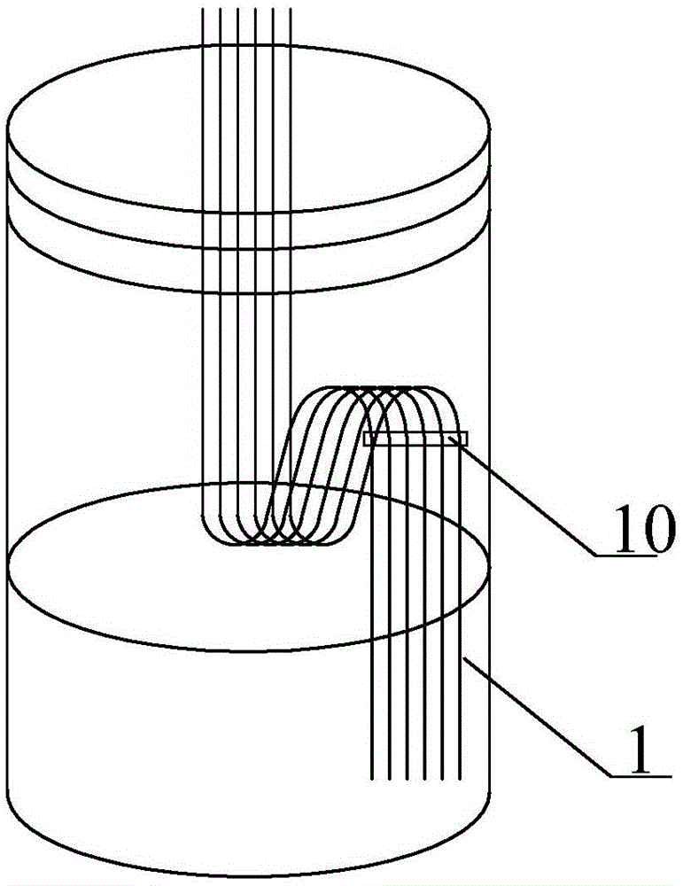
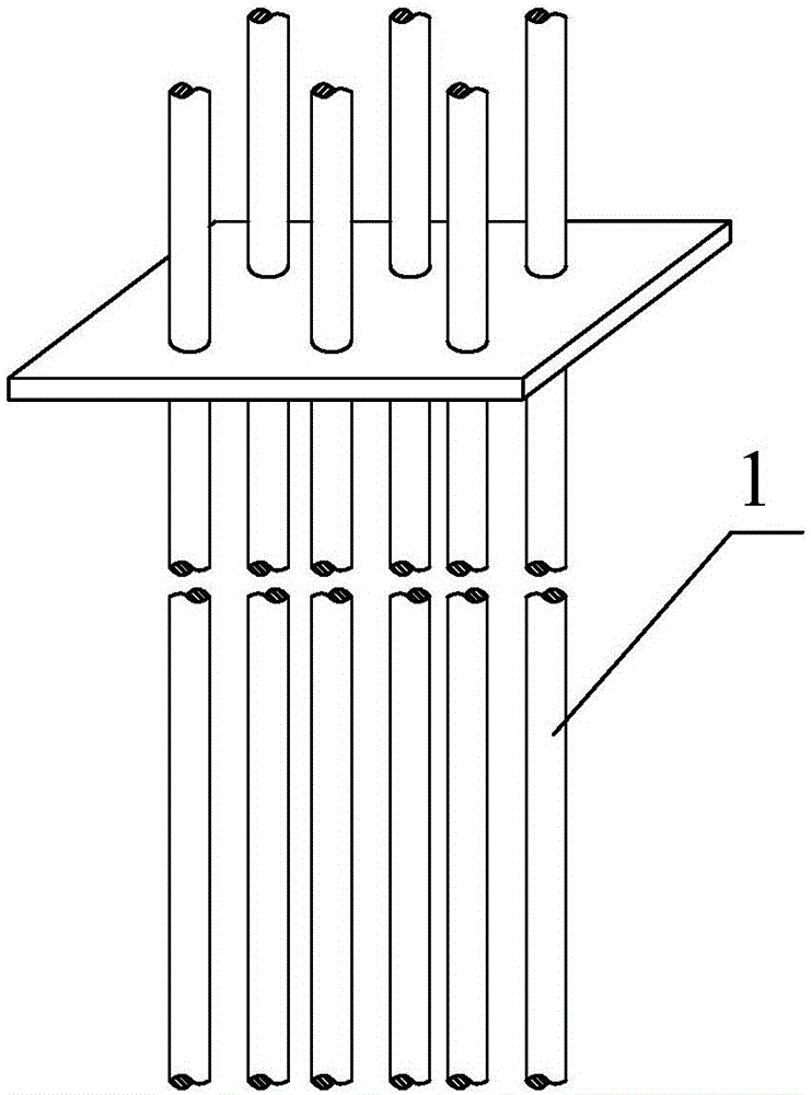
[0118] Such as Figure 6 to Figure 9 As shown, the heat transfer and cooling system based on the enclosure structure in this embodiment includes an enclosure structure and a power transmission cable 1 laid along the inner wall of the enclosure structure. The power transmission cable 1 is laid in a bent shape along the vertical direction. The power transmission cable 1 It is preferably laid in the region of the envelope close to the inner wall of the shade.

[0119] In the embodiment of the present invention, "bent shape" should be understood as the power transmission cable 1 is different from the prior art extending substantially linearly from top to bottom, but in a zigzag shape, a curved shape, or a combination of a zigzag line and a curve way, extending back and forth in the circumferential direction from top to bottom.

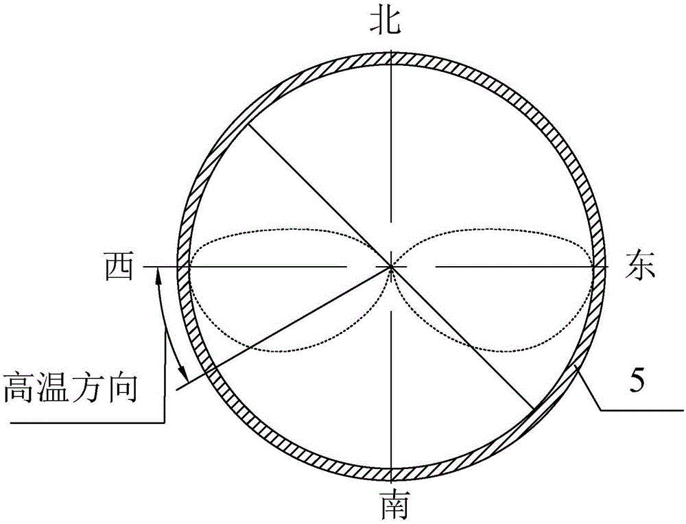
[0120] In this embodiment, the enclosure structure is a circular tower 5 with a horizontal section. In other embodiments, the enclosure structure can be ...

Embodiment 2

[0202] The heat transfer and cooling system of this embodiment is the same as the first embodiment in terms of its inventive concept, basic implementation, working principle and beneficial effects. For the sake of brevity, only the differences from the first embodiment are described here. Description of Embodiment 1.

[0203] The difference between this embodiment and the first embodiment lies in that the specific shape of the power transmission cable 1 bent along the vertical direction is different.

[0204] Such as Figure 17 As shown, in this embodiment, the power transmission cable 1 includes a plurality of twisted sections arranged from top to bottom in the vertical direction, and each twisted section includes two inclined subsections (ie, the first inclined subsection 11 and the second inclined subsection 11). Two inclined subsections 12) and the transition subsection 13 between the two inclined subsections, the angle between the first inclined subsection 11 and the sec...

Embodiment 3

[0208] The heat transfer and cooling system of this embodiment is the same as the first embodiment in terms of its inventive concept, basic implementation, working principle and beneficial effects. For the sake of brevity, only the differences from the first embodiment are described here. Description of Embodiment 1.

[0209] The difference between this embodiment and the first embodiment lies in that the specific shape of the power transmission cable 1 bent along the vertical direction is different.

[0210] Such as Figure 18 As shown, in this embodiment, the power transmission cable 1 also includes a plurality of twisted sections arranged from top to bottom in the vertical direction, and each twisted section includes two inclined subsections (ie, the first inclined subsection 11 and the first inclined subsection 11). The second inclined subsection 12) and the transition subsection 13 between the two inclined subsections, the angle between the first inclined subsection 11 a...


PUM

PropertyMeasurementUnit
thicknessaaaaaaaaaa
emissivityaaaaaaaaaa

Abstract

The invention relates to a retaining structure-based heat transferring and dissipating system and a wind generator set. The heat transferring and dissipating system comprises a retaining structure and a power transmission cable, wherein the power transmission cable is laid along the vertical direction of the inner wall of the retaining structure, and is laid in a shady surface region of the retaining structure. According to the retaining structure-based heat transferring and dissipating system, the surface temperature of the power transmission cable in the retaining structure is effectively lowered; the service life of the power transmission cable is prolonged; the operation safety of power transmission is ensured; the over-temperature problem of the power transmission cable in a tower drum of the wind generator set in a high-temperature natural geographical environment is solved with ''green'' and ''zero-energy consumption'' modes in an assist manner; and the system safety of power transmission is improved.

Description

technical field [0001] The invention relates to the technical field of power transmission, in particular to a heat transfer and cooling system based on an enclosure structure and a wind power generating set. Background technique [0002] 1. Physical overview of the application of wind turbine tower power transmission cables [0003] In recent years, with the continuous increase of the capacity of wind turbines, the current level transmitted by the power transmission cables of wind turbine towers is getting larger and larger, and the diameter and weight of power transmission cables are also increasing. Factors such as heating caused by current during operation and cost pressure caused by rising copper prices are issues of great concern to complete machine designers. [0004] 1. General requirements for power transmission cable design [0005] The design and manufacture of power transmission cables should fully consider the installation and operation characteristics of the w...

Claims


Application Information

Patent Timeline
Patent Type & Authority Applications(China)
IPC IPC(8): H02G3/00H02G3/03H02G3/32F03D11/00
CPCH02G3/03Y02E10/728H02G3/32F05B2260/221F05B2260/231Y02E10/72Y02T50/60H02G3/00F03D13/20F03D80/85F16L59/028F28F13/18F28F2245/00
Inventor 马盛骏马万顺
Owner XINJIANG GOLDWIND SCI & TECH
Why Eureka
Try Eureka