Environment-friendly efficient waste incinerator

A waste incinerator, high-efficiency technology, applied in the direction of incinerators, combustion methods, combustion types, etc., can solve the problems of waste of resources, rapid oxidation of combustion furnaces, waste of resources, etc., to prevent the generation of harmful gases, high equipment utilization, The effect of increasing the combustion rate

Active Publication Date: 2016-01-20
都安通达环保设备制造厂(普通合伙)
View PDF7 Cites 20 Cited by
  • Summary
  • Abstract
  • Description
  • Claims
  • Application Information

AI Technical Summary

Problems solved by technology

However, there are many defects in garbage landfill: first, the construction of garbage landfill takes up a lot of land, land is a non-renewable resource, and land resources are relatively tight; second, it pollutes the environment and increases management costs; After organic matter and batteries enter the landfill, the toxic leachate produced will seriously pollute the soil and groundwater. From the perspective of environmental protection, it is necessary to establish a landfill leachate anti-seepage, collection and treatment system. This will increase the technical difficulty, but also increase the investment, the landfill operation is complicated, and the management is difficult. In addition, the methane, hydrogen sulfide and other wastes in the landfill must also be treated to ensure that the explosion-proof and environmental protection requirements are met; 3. Waste of resources, A large amount of garbage is piled up in landfills, and some of the materials and energy cannot be used, which causes a waste of resources to a certain extent.
During the use of traditional garbage incinerators, garbage is put on the grate in the incinerator for incineration. However, when the garbage on the grate is burning, the newly put in garbage instantly covers the burning garbage. It is easy to extinguish the flame, resulting in unstable temperature in the furnace, insufficient garbage incineration, and insufficient garbage incineration will easily produce harmful gases
[0004] At the same time, the composition of the garbage is complex, and various combustibles have different properties, which makes the phenomenon of clinker, slag, sintering and other phenomena during the incineration process of the garbage, and the combustion rate is low.
The combustible gas in the flue gas and the combustible matter in the fly ash cannot be completely incinerated, and there are many harmful components in the finally discharged flue gas, which pollutes the environment
Garbage is sometimes incompletely burned, and black smoke will be generated due to incomplete combustion, causing secondary pollution to the environment. At the same time, due to the high temperature, the combustion furnace oxidizes quickly and has a short life, and the heat generated by combustion is not used.

Method used


Image

  • Environment-friendly efficient waste incinerator
  • Environment-friendly efficient waste incinerator
  • Environment-friendly efficient waste incinerator

Examples


Embodiment 1

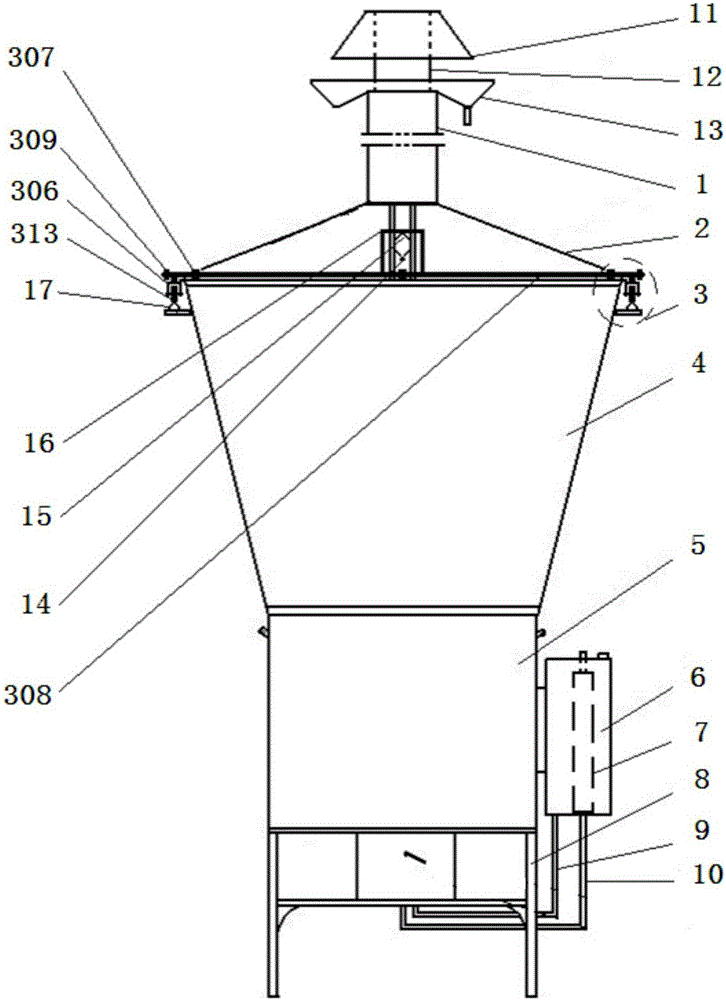
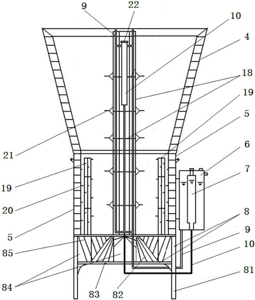
[0031] An environment-friendly and high-efficiency garbage incinerator comprises a lower furnace body 5, an upper furnace body 4, an inner chimney 18, a base 8, a furnace cover 2 and an outer chimney 1. The upper furnace body 4 and the lower furnace body 5 of the furnace body are welded as one, and the inner chimney 18 is arranged in the middle of the lower furnace body 5 and the upper furnace body 4. The inner chimney 18 is in the shape of a long cage and consists of multiple vertical seamless water pipes, Reinforcing bar and transverse reinforcing bar ring are welded with a certain distance between phase; Lower body of furnace 5 and interior chimney 18 constitute combustion chamber, and lower furnace body 5 and upper furnace body 4 are provided with refractory bricks around, and the bottom of lower furnace body 5 is connected with base 8, and the upper and lower sides of base 8 are open. A furnace cover 2 is arranged above the upper furnace body 4, and an outer chimney 1 is ...

Embodiment 2

[0034] The difference from Example 1 is that the lower furnace body 5 also includes a corner cage 19 and a lower furnace body hook 20, and the corner cages 19 are distributed in corresponding corners or surfaces of the lower furnace body 5; the corner cages 19 is welded by a certain distance between a plurality of vertical steel bars and transverse steel rings, and hooks are provided outside the corner cage 19; the lower furnace body hooks 20 are evenly distributed on the inner wall of the lower furnace body 5, and the corner cages 19 are respectively It is welded and fixed with the lower furnace body hook 20 and the base 8. The corner cage 19 and the hook on the corner cage 19 can also support the garbage, avoiding the excessive accumulation of garbage in the corner of the body of heater and insufficient oxygen supply, so that the garbage in the body of the furnace burns without dead ends, and the garbage burns completely.

[0035] The working principle of this embodiment is ...

Embodiment 3

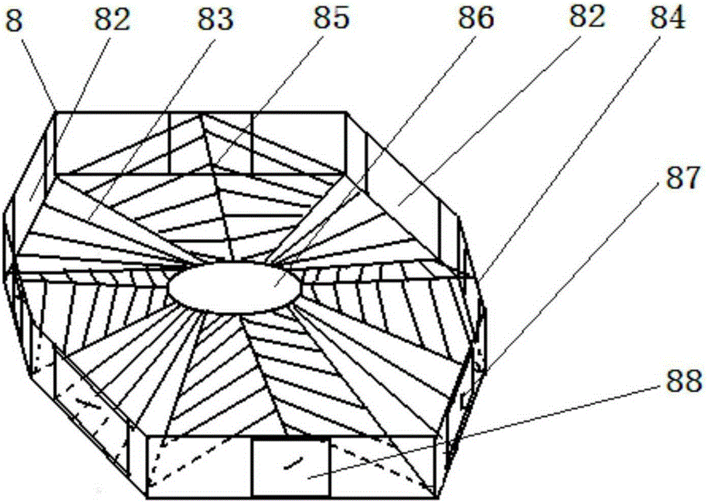
[0037] The difference from Example 1 is that the base 8 is provided with a furnace bridge and a furnace foot 81, the furnace foot 81 is fixed under the base 8, and there are slag discharge ports 82 and ignition ports 84 around the base 8, and each slag discharge port A slagging door 87 and an ignition door 88 are correspondingly arranged on the port 82 and the ignition port 84; the middle part of the base 8 is also provided with a chimney air inlet 86, and the inner chimney 18 is fixed above it. The furnace bridge is composed of an inclined furnace bridge 83 and a ∧-shaped furnace bridge 85; the inclined furnace bridge 83 is welded with the slag outlet 82 and the inner chimney 18 by a plurality of oblique steel bars at a certain distance; The ∧-shaped furnace bridge 85 is welded with the ∧-shaped ejector pin and the ignition port 84 by a plurality of steel bars with different lengths at a certain distance. The setting of the ∧-shaped furnace bridge 85 is convenient for ignitio...


PUM


Abstract

The invention discloses an environment-friendly efficient waste incinerator. The environment-friendly efficient waste incinerator comprises a lower incinerator body part, an upper incinerator body part, an internal chimney, a base, an incinerator cover and an external chimney. The upper incinerator body part and the lower incinerator body part of an incinerator body are welded into a whole. The internal chimney is arranged in the middle of the lower incinerator body part and the middle of the upper incinerator body part. A combustion chamber is formed by the lower incinerator body part and the internal chimney. Refractory bricks are arranged on the periphery of the lower incinerator body part and the periphery of the upper incinerator body part. The bottom end of the lower incinerator body part is connected with the base. Both the upper surface and the lower surface of the base are open. The incinerator cover is arranged on the upper incinerator body part. The external chimney is arranged at the top of the incinerator cover in a connected mode. A water tank is arranged outside the lower incinerator body part. An oil tank is further arranged in the water tank. A water pipe and an oil pipe are arranged in the internal chimney. The water pipe is communicated with the water tank. The oil pipe is communicated with the oil tank. According to the environment-friendly efficient waste incinerator, oil in the oil pipe can be gasified by means of heat generated during waste combustion, so that waste on the upper portion of the incinerator body can be combusted for the second time, continuous waste combustion is achieved, incineration is thorough and rapid, and the incineration effect is good; pollution to the environment is small, and the environment-friendly efficient waste incinerator is suitable for waste treatment in village and town communities, schools and hospitals.

Description

technical field [0001] The invention relates to a garbage treatment device, in particular to an environment-friendly and high-efficiency garbage incinerator. Background technique [0002] With the continuous development of the economy, the amount of domestic waste generated in towns and villages has also doubled every year. The traditional way of garbage disposal is to build a landfill to landfill the garbage. However, there are many defects in garbage landfill: first, the construction of garbage landfill takes up a lot of land, land is a non-renewable resource, and land resources are relatively tight; second, it pollutes the environment and increases management costs; After organic matter and batteries enter the landfill, the toxic leachate produced will seriously pollute the soil and groundwater. From the perspective of environmental protection, it is necessary to establish a landfill leachate anti-seepage, collection and treatment system. This will increase the technica...

Claims


Application Information

Patent Timeline
Patent Type & Authority Applications(China)
IPC IPC(8): F23G5/14F23G5/46F23G5/44
Inventor 朱肖州
Owner 都安通达环保设备制造厂(普通合伙)
Why Eureka
Try Eureka