

Coated cutting tool
A coating cutting tool and coating technology, applied in the field of coating cutting tools, can solve problems such as insufficient oxidation resistance
- Summary
- Abstract
- Description
- Claims
- Application Information
AI Technical Summary
Problems solved by technology
Method used
Image

Examples
Embodiment 1
[0052] Embodiment 1 (the present invention)
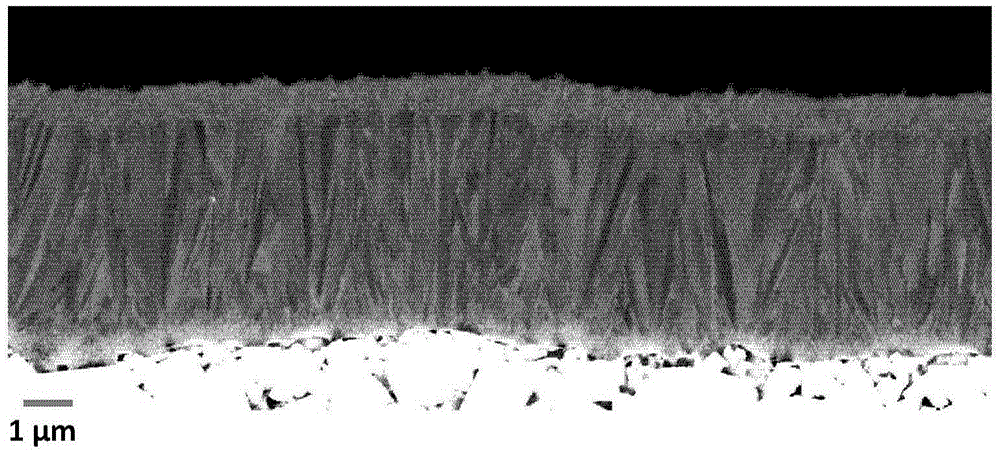
[0053] A coated cutting tool according to one embodiment of the present invention was fabricated. First, a cemented carbide R365-1505ZNE-KM substrate was fabricated. The substrates were then coated with the deposition process as disclosed in Table 1.
[0054] Manufacture substrate by pressing powder and sintering compact, its composition is 7.61wt% Co, 1.15wt% Ta, 0.27wt% Nb and balance WC, Hc value is 14.5kA / m (according to DINIEC60404-7, using FoersterKoerzimatCS1.096 measurement), hardness HV3 is 1550GPa. Prior to deposition, the substrate edges were rounded to about 35 μm by wet blasting. A coating was deposited on the substrate by CVD consisting of first a Ti(C,N) layer with a total thickness of about 4.8 μm consisting of the layer sequence 0.3 μm TiN, 4.1 μm MTCVDTi(C,N) and 0.4 μm HTCVDTi(C, N) composition, followed by a Ti(C,N,O) bond layer of 0.8 μm and α-Al with a thickness of 3.7 μm 2 o 3 layer, and finally a 1.2...
Embodiment 2
[0059] Embodiment 2 (prior art)
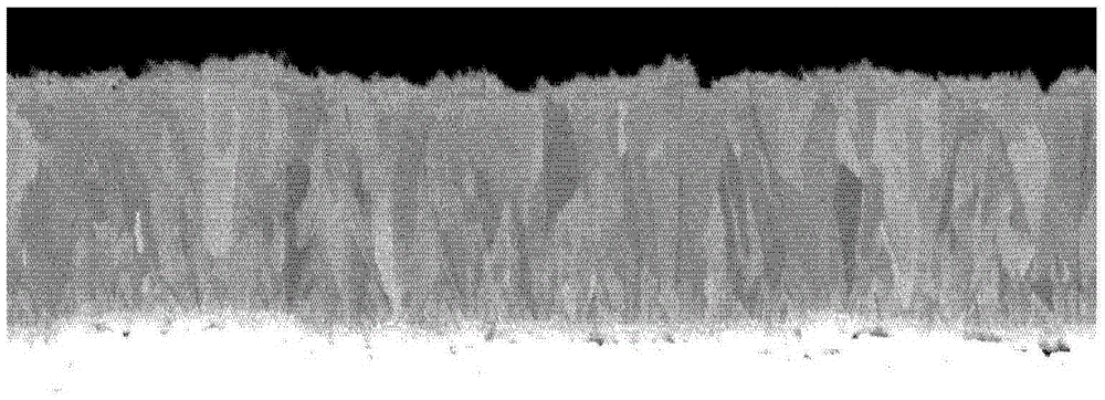
[0060] A coated cutting tool representative of the state of the art was fabricated for use as a reference. In Table 2 the deposition conditions used to grow the coatings are described. exist figure 2 A cross-sectional view of as-deposited Ti(C,N) is shown in .
[0061] First, a cemented carbide R365-1505ZNE-KM substrate having the same composition as disclosed in Example 1 above was fabricated. Prior to coating deposition, the substrate edges were rounded to about 35 μm by wet blasting. A coating consisting of the layer sequence 0.3 μm TiN, 4.7 μm MTCVDTi(C,N), 0.4 μm HTCVDTi(C,N), 0.6 μm tie layer containing Ti(C,O), thickness α-Al of about 3.4 μm 2 o 3 layer, and 1.4μm TiN / TiC / TiN / TiC / TiN colored layer.
[0062] After deposition, the coated cutting tool referred to as Sample 2A was wet blasted to remove the colored layer on the rake face, and the coated cutting tool referred to as Sample 2B was edgeline brushed to remove the colore...
Embodiment 3
[0065] Embodiment 3 (the present invention)
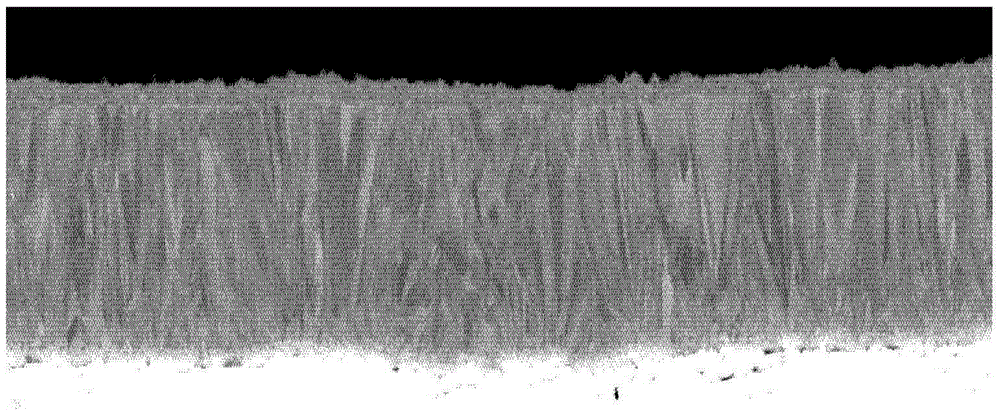
[0066] As shown in Tables 1 and 2, according to Example 1 with the corresponding MTCVDTi(C,N) layer, but with the tie layer corresponding to Example 2, α-Al 2 o 3 layer and colored layer to manufacture coated cutting tools. The cross-sectional view of deposited Ti(C,N) is shown in image 3 middle.
[0067] As explained in detail below, MTCVDTi(C,N) layers (see Table 4) and α-Al 2 o 3 The texture coefficient TC(hkl) of the columnar grains of the layer (see Table 5). MTCVDTi(C,N) has a sum of TC(311) and TC(422) of 3.84. α-Al 2 o 3 X-ray diffraction measurements of the layer showed a sum of TC(0012) and TC(104) of 2.17.
[0068] After deposition, the coated cutting tool referred to as Sample 3A was wet blasted to remove the colored layer on the rake face, and the coated cutting tool referred to as Sample 3B was edgeline brushed to remove the colored layer on the rake face. coating becomes uniform.
[0069] Table 1
[00...
PUM
| Property | Measurement | Unit |
|---|---|---|
| Thickness | aaaaa | aaaaa |
| Thickness | aaaaa | aaaaa |
| Particle size | aaaaa | aaaaa |
Abstract
Description
Claims
Application Information