Dilute nitric acid device adopting double pressure method

A technology of double pressurization, dilute nitric acid, applied in the direction of nitric acid, sustainable manufacturing/processing, nitrogen oxides/oxyacids, etc. Less than the design average value and other problems, to achieve the effect of reducing steam consumption and improving the comprehensive recovery rate of heat energy

Active Publication Date: 2016-02-10
HANGZHOU LONGSHAN CHEM CO LTD
View PDF4 Cites 4 Cited by
  • Summary
  • Abstract
  • Description
  • Claims
  • Application Information

AI Technical Summary

Problems solved by technology

[0004] 1. In the high temperature season, the output cannot reach the design average value. The main reason is that the air pumping volume of the air axial flow compressor in the "four-in-one unit" is too small, which restricts the output of nitric acid finished products of the production device.
[0005] 2. Due to the design of the tail gas turbine in the double-pressurized dilute nitric acid device, the temperature of the outlet NOx tail gas is generally higher than the design value of 105°C, and in some devices it is as high as 170°C or more. The high-temperature tail gas is sent directly to Ф1. 2×62m exhaust chimneys are discharged at high altitude, and the low-temperature heat energy of the exhaust gas cannot be fully recovered and utilized
The main reasons for the high exhaust gas temperature are 1. The exhaust gas temperature at the waste heat boiler outlet in the device is 480°C higher, resulting in a 370-380°C higher tail gas temperature at the tail gas inlet; 2. At the same time, the actual heat recovery efficiency of the exhaust gas turbine is also low. There is a certain gap with the design value, so the temperature of the exhaust gas at the outlet is high

Method used


Image

  • Dilute nitric acid device adopting double pressure method
  • Dilute nitric acid device adopting double pressure method
  • Dilute nitric acid device adopting double pressure method

Examples


Embodiment Construction

[0024] The present invention will be further described in detail below in conjunction with the accompanying drawings and through the examples. The following examples are to explain the present invention and the present invention is not limited to the following examples.

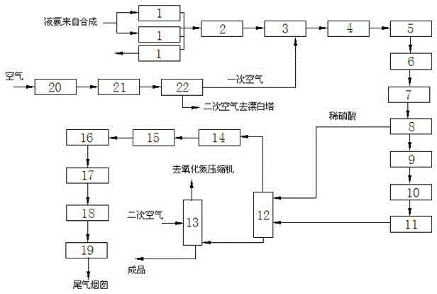
[0025] see Figure 1 to Figure 3 , the present invention includes an ammonia evaporator 1, an ammonia filter 2, a mixer 3, an ammonia oxidation furnace 4, a waste heat boiler 5, a high-temperature gas heat exchanger 6, a low-pressure reaction water cooler 7, a nitrogen oxide separator 8, and a nitrogen oxide compressor 9. First tail gas preheater 10, high pressure reaction water cooler 11, absorption tower 12, bleaching tower 13, tail gas separator 14, cooler 15, second tail gas preheater 16, ammonia reduction reactor 17, tail gas expander 18. Ammonia superheater device 19, air filter 20, blast dehumidification device 21, axial flow compressor 22.

[0026] Ammonia evaporator 1, ammonia filter 2, mixer 3, amm...


PUM


Abstract

The invention relates to a dilute nitric acid device adopting a double pressure method, and the device can increase output at the high temperature season and improve heat energy recovery efficiency. The device is characterized in that a gaseous ammonia outlet of an ammonia evaporator is communicated with a cold fluid inlet of a second ammonia superheater; a cold fluid outlet of the second ammonia superheater is communicated with a cold fluid inlet of a first ammonia superheater; the gaseous ammonia outlet of the ammonia evaporator is communicated with the cold fluid inlet of the first ammonia superheater; a gaseous ammonia inlet of an ammonia filter is communicated with a cold fluid outlet of the first ammonia superheater; a tail gas outlet of a tail gas expansion machine is communicated with a thermal fluid inlet of the second ammonia superheater; an air filter, an air blast dehumidification device and an axial flow compressor are sequentially connected; a gas outlet of the air filter is communicated with a gas inlet of an air blower; a gas outlet of the air blower is communicated with a thermal fluid inlet of a heat exchanger; a thermal fluid outlet of the heat exchanger is communicated with an inlet of a demister; an outlet of the demister is communicated with an inlet of the axial flow compressor; a cold fluid outlet of the heat exchanger, a cold water pump, a refrigerating unit and a cold fluid inlet of the heat exchanger are sequentially communicated.

Description

technical field [0001] The invention relates to a double pressurized dilute nitric acid device. Background technique [0002] The double-pressurization nitric acid plant adopts the double-pressurization method to produce nitric acid, such as the Chinese patent with the application number 201420293262.7 and the name of the double-pressurization nitric acid production device. [0003] There are following disadvantages in the present double pressurized nitric acid plant: [0004] 1. In the high temperature season, the output cannot reach the design average value. The main reason is that the air pumping volume of the air axial flow compressor in the "four-in-one unit" is too small, which restricts the output of finished nitric acid products of the production device. [0005] 2. Due to the design of the exhaust gas turbine in the double-pressurized dilute nitric acid device, the temperature of the outlet NOx exhaust gas is generally higher than the design value of 105°C, and in ...

Claims


Application Information

Patent Timeline
Patent Type & Authority Applications(China)
IPC IPC(8): C01B21/38
CPCY02P20/129Y02P20/10
Inventor 金沛灿何肖廉黎志敏
Owner HANGZHOU LONGSHAN CHEM CO LTD
Why Eureka
Try Eureka