Smoke waste-heat utilization system based on selective catalytic reduction (SCR) denitration device

A flue gas waste heat and denitrification technology, applied in liquid degassing, preheating, feed water heaters, etc., can solve the problems of lower exhaust gas temperature boiler thermal efficiency than the design value, lower energy utilization efficiency, and increased water consumption of desulfurization towers, etc. Achieve the effects of controlling NOx emissions, improving utilization efficiency, and reducing water consumption

Active Publication Date: 2016-02-10
TAIYUAN UNIV OF TECH
View PDF5 Cites 10 Cited by
  • Summary
  • Abstract
  • Description
  • Claims
  • Application Information

AI Technical Summary

Problems solved by technology

The high exhaust gas temperature leads to a lower thermal efficiency of the boiler than the design value, which seriously reduces the energy utilization efficiency, and also causes the efficiency of the dust collector to decrease and the water consumption of the desulfurization tower to increase

Method used


Image

  • Smoke waste-heat utilization system based on selective catalytic reduction (SCR) denitration device

Examples


Embodiment 1

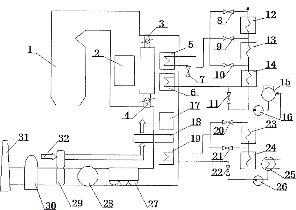
[0011] see figure 1 , a flue gas waste heat utilization system based on an SCR denitration device, which includes a boiler 1, an economizer 2, an SCR denitration device 17, an air preheater 18, a front air preheater 29, a dust collector 27, and an induced draft fan 28. Desulfurization device 30, chimney 31, flue gas waste heat recovery system and feed water heat recovery system. The flue gas waste heat recovery system includes a primary heater 6, a secondary heater 5 and a flue gas cooler 19. The The feed water recuperation system includes a condenser 25, a feed water pump 16, a deaerator 15, a condensate water pump 26, a first high pressure heater 12, a second high pressure heater 13, a third high pressure heater 14, a first low pressure heater 23 and The second low-pressure heater 24, the economizer 2 is arranged in the tail flue of the boiler 1, and its heat inlet end is connected with the heat outlet end of the boiler 1, and the heat outlet end of the economizer 2 is conne...

Embodiment 2

[0013] A flue gas bypass is added to the flue of the economizer 2, that is, a flue gas bypass baffle 3 is added at the flue of the inlet of the economizer 2, the bypass flue gas is not cooled by the economizer, and the outlet of the economizer 2 is cooled The gas is mixed with it and enters the SCR denitrification device 17 together. In this embodiment, when the requirement of maintaining the flue gas temperature at the inlet of the SCR denitrification device 17 at 316° C. to 420° C. is met, the variation range of the bypass flue gas fraction is determined.

[0014] The temperature difference between the cold air at the inlet of the air preheater 18 and the temperature of the flue gas from the air preheater 18 is relatively large. Using the front air preheater 29 to heat the cold air can increase the temperature of the air at the inlet of the air preheater 18 and reduce its temperature. The heat exchange temperature difference with the flue gas can be heated by utilizing the w...

Embodiment 3

[0017] When the load is high or the operating conditions change so that the flue gas temperature at the furnace outlet is too high, it is required that the flue gas temperature at the outlet of the economizer 2 should not be higher than 420°C. The secondary heater 5 and the primary heater 6 absorb the heat of the flue gas so that the flue gas temperature drops below 420°C after meeting with the mainstream flue gas behind the main flue baffle 4 and before entering the SCR denitrification device 17. According to the water supply bypass outlet water temperature, open the corresponding high-pressure heater bypass valve, and merge into the water supply main channel;

[0018] When the load is reduced to about 50% and the flue gas temperature at the furnace outlet is too low, it is required that the flue gas temperature at the outlet of the economizer 2 should not be lower than 320°C. Heat release, so that the combined flue gas temperature after the main flue valve is higher than 320...


PUM


Abstract

The invention discloses a smoke waste-heat utilization system based on a selective catalytic reduction (SCR) denitration device. The smoke waste-heat utilization system comprises a boiler (1), an economizer (2), the SCR denitration device (17), an air preheater (18), a front air preheater (29), a dust remover (27), an induced draft fan (28), a desulfurizer (30), a chimney (31), a smoke waste-heat recovery system and a water supply regenerative system. The smoke waste-heat recovery system comprises a first-grade heater (6), a second-grade heater (5) and a smoke cooler (19). The water supply regenerative system comprises a condenser (25), a water supply pump (16), a deaerator (15) and a condensate water pump (26). According to the smoke waste-heat utilization system, it can be ensured that the SCR denitration device is put into operation continuously, and emission of NOx is controlled; correspondingly, waste heat contained in temperature increasing of exhausted smoke needs to be recycled, so that the energy use efficiency is improved greatly, the efficiency of the dust remover is improved, and the water consumption of the desulfurizer is reduced.

Description

technical field [0001] The invention relates to the technical field of coal-fired power plant boilers and pollutant control, in particular to a flue gas waste heat utilization system based on an SCR denitrification device. Background technique [0002] The working temperature of the SCR catalyst has relatively strict requirements, and both high and low temperatures have clear restrictions. If the temperature is too high, the surface of the catalyst will be sintered, and part of the active components will be lost, thereby reducing the activity of the catalyst. According to the characteristics of the product, the flue gas temperature at the inlet of the SCR is not allowed to exceed 427°C during operation. If this temperature exceeds this temperature, the catalyst will permanently fail. If the temperature is too low, it will affect the activity of the catalyst. If it is lower than 300°C, under the action of the same catalyst, the SCR will also generate ammonium bisulfate as a ...

Claims


Application Information

Patent Timeline
Patent Type & Authority Applications(China)
IPC IPC(8): F22D1/02F22D1/50F23L15/00F23J15/02F23J15/06
CPCY02E20/34
Inventor 崔志刚马素霞宋凯杨建新唐晓梅索疆舜
Owner TAIYUAN UNIV OF TECH
Why Eureka
Try Eureka