

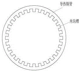
Manufacturing method of heat conduction copper pipe with inner groove
A manufacturing method and technology of heat-conducting copper tubes, applied in the field of powder metallurgy, can solve problems such as high cost, poor thermal conductivity, and complicated methods, and achieve the effects of low production cost, simple steps, and broad application prospects
- Summary
- Abstract
- Description
- Claims
- Application Information
AI Technical Summary
Problems solved by technology
Method used
Image

Examples
Embodiment 1
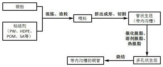
[0027] Add 40vol.% of polymer binder (50wt.% of PW, 45wt.% of PE and 5wt.% of SA) to the copper powder with particle size D50 of 10 μm. The metal powder is heated to 160°C, and then PW, PE and SA are gradually added. After mixing evenly, the granular feed is made by a granulator. Formed by an extruder at 120°C to produce a tubular green body with an inner groove (inner diameter? 16mm, outer diameter? 20mm), and then cut the tubular green body into a length of 300mm. Soak the green body in a n-hexane solution at 40°C and keep it warm for 24 hours to degrease the solvent. Then take out the green body, put it into the degreasing sintering furnace after drying. Pass flowing argon into the debinding sintering furnace, and remove the remaining binder by thermal debinding at 450°C. Then the temperature was gradually raised to 850°C, and the temperature was lowered after sintering for 2 hours. The result is a dense copper tube with internal grooves.
Embodiment 2
[0029] Add 40vol.% polymer binder (86wt%POM, 6wt%PE, 6wt%EVA and 2wt%SA) to the copper powder with a particle size D50 of 10μm, and put the metal powder in the internal mixer Heat to 180°C, then gradually add PW, PE and SA. After mixing evenly, the granular feed is made by a granulator. Formed by an extruder at 160°C to produce a tubular green body with an inner groove (inner diameter? 16mm, outer diameter? 20mm), and then cut the tubular green body into a length of 300mm. The green body is degreased with oxalic acid in a degreasing furnace. Then put into the degreasing sintering furnace. Flowing argon gas is introduced into the debinding sintering furnace, and the remaining binder is removed by thermal debinding at 500°C. Then the temperature was gradually raised to 800°C, and the temperature was lowered after sintering for 3 hours. The result is a dense copper tube with internal grooves.
[0030] The patent of the present invention proposes a method of manufacturing hea...
PUM
| Property | Measurement | Unit |
|---|---|---|
| particle diameter | aaaaa | aaaaa |
| tensile strength | aaaaa | aaaaa |
Abstract
Description
Claims
Application Information