
Silicon-based electro-optical modulator of micro-cavity coupling multimode interferometer

An electro-optic modulator and multi-mode interference technology, which is applied in the field of integrated photonics, can solve the problems of limited transmission bandwidth, inability to load communication network transmission tasks, and aggravated parasitic effects, and achieve low cost, compact structure, and easy design and preparation. Effect

Active Publication Date: 2016-03-16
SHANGHAI JIAO TONG UNIV
View PDF4 Cites 7 Cited by
  • Summary
  • Abstract
  • Description
  • Claims
  • Application Information

AI Technical Summary

Problems solved by technology

However, in terms of short-distance communication, in view of the fact that the chip size is getting smaller and smaller, the on-chip processing function is getting stronger and faster, and the information processing speed is getting faster and faster, the traditional electrical interconnection system is facing a series of problems such as limited transmission bandwidth and intensified parasitic effects. , can no longer bear the burden of transmission in future communication networks, and optical interconnection has become the best solution to replace metal electrical interconnection due to its advantages of low delay, low power consumption, low crosstalk, and large bandwidth.

Method used


Image

  • Silicon-based electro-optical modulator of micro-cavity coupling multimode interferometer
  • Silicon-based electro-optical modulator of micro-cavity coupling multimode interferometer
  • Silicon-based electro-optical modulator of micro-cavity coupling multimode interferometer

Examples


Embodiment Construction

[0021] The embodiments of the present invention will be described in detail below in conjunction with the accompanying drawings and Examples. This embodiment is implemented on the premise of the technical solution of the present invention, and detailed implementation methods and operating procedures are provided, but the protection scope of the present invention is not limited to Examples described below.

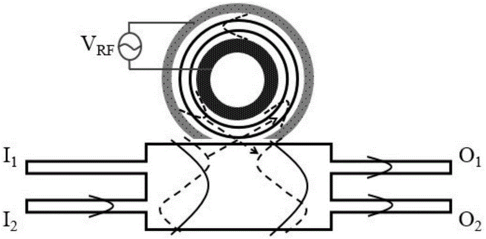
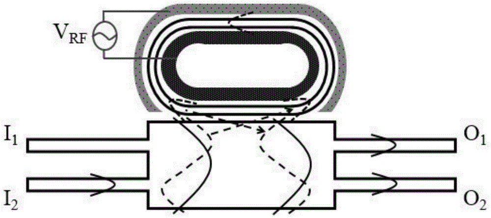
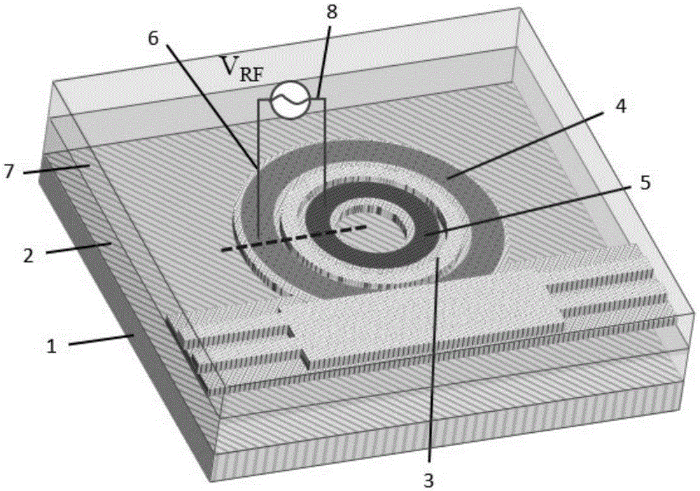
[0022] see first figure 1 and figure 2 , figure 1 It is a silicon-based electro-optic modulator embodiment 1 of a microcavity coupled multimode interferometer of the present invention - a schematic structural diagram of a microring cavity coupled multimode interferometer, figure 2 It is a silicon-based electro-optic modulator embodiment 2 of a microcavity coupled multi-mode interferometer of the present invention-a schematic structural diagram of a racetrack-type micro-resonator coupled multi-mode interferometer. It can be seen from the figure that the silicon-based ele...


PUM

PropertyMeasurementUnit
thicknessaaaaaaaaaa
thicknessaaaaaaaaaa
thicknessaaaaaaaaaa

Abstract

The invention relates to a silicon-based electro-optical modulator of a micro-cavity coupling multimode interferometer. The silicon-based electro-optical modulator comprises an adjustable miniature resonant cavity and a multimode interferometer. The input light is excited into two modes in a multimode interference wave-guide, wherein the light of one mode is coupled to a side miniature resonant cavity and the light of the other mode is not coupled to the miniature resonant cavity. The above two paths of light intervene with each other in the multimode wave-guide. In this way, the output light has an asymmetric resonance spectrum. Through modulating the miniature resonant cavity, the highly linear intensity modulation is ensured. The silicon-based electro-optical modulator has a broad application prospect in the optical communication and microwave photon signal processing field.

Description

technical field [0001] The invention relates to integrated photonics, in particular to a silicon-based electro-optic modulator of a microcavity coupled multimode interferometer, which utilizes one path of coupled resonant light and another path of nonresonant light to interfere in the multimode interferometer, and obtains non-resonant light at the output port. Symmetrical resonant spectrum, high linearity intensity modulation can be achieved by modulating the micro-resonator. Background technique [0002] With the rapid increase in the amount of information obtained in modern society, people have put forward an urgent need for high-speed, large-capacity communication networks. Optical fiber communication has become the most mainstream communication method in the world due to its high bandwidth and high confidentiality. However, in terms of short-distance communication, in view of the fact that the chip size is getting smaller and smaller, the on-chip processing function is g...

Claims


Application Information

Patent Timeline
Patent Type & Authority Applications(China)
IPC IPC(8): G02F1/01
CPCG02F1/011G02F1/0113
Inventor 王敏娟周林杰周砚扬陈建平
Owner SHANGHAI JIAO TONG UNIV
Learn More