A Solar Sensor Based on Photovoltaic Micro Energy Harvesting

A solar sensor and micro-energy technology, applied in current collectors, photovoltaic power generation, electric vehicles, etc., can solve problems such as low photoelectric conversion efficiency of solar sensors, limited field of view of solar sensor products, and difficulty in maintaining communication, etc., to achieve Reduce design difficulty and device cost, ultra-high photoelectric conversion efficiency, and realize the effect of miniaturization design

Active Publication Date: 2018-05-01
BEIJING INST OF CONTROL ENG
View PDF5 Cites 0 Cited by
  • Summary
  • Abstract
  • Description
  • Claims
  • Application Information

AI Technical Summary

Problems solved by technology

[0004] The existing photovoltaic self-powered solar sensor has low photoelectric conversion efficiency, and its energy harvesting requires a high start-up voltage, and has no energy storage unit, making it unable to work under the conditions of large field of view and low energy input, which limits the efficiency of solar energy. Field of view range of sensor products
Periodic wireless communication requires continuous energy supply, and the solar sensor requires instantaneous large energy consumption when receiving signals wirelessly. The existing photovoltaic self-powered solar sensor does not have an energy storage unit. When the field of view is not good, especially when it is out After the field of view, it is impossible to provide energy to make the wireless communication module work, resulting in no response in communication, and it is difficult for the control computer to determine the status of the product. Even when short-term interactive communication is carried out in the field of view, due to instantaneous energy consumption and other reasons, the energy will not make ends meet. , communication is difficult to maintain
In addition, due to the low photoelectric conversion efficiency of the existing photovoltaic self-powered solar sensors, large-area photovoltaic cells have to be used to meet the load work, which cannot meet the miniaturization and miniaturization requirements of solar sensors.

Method used


Image

  • A Solar Sensor Based on Photovoltaic Micro Energy Harvesting
  • A Solar Sensor Based on Photovoltaic Micro Energy Harvesting
  • A Solar Sensor Based on Photovoltaic Micro Energy Harvesting

Examples


Embodiment

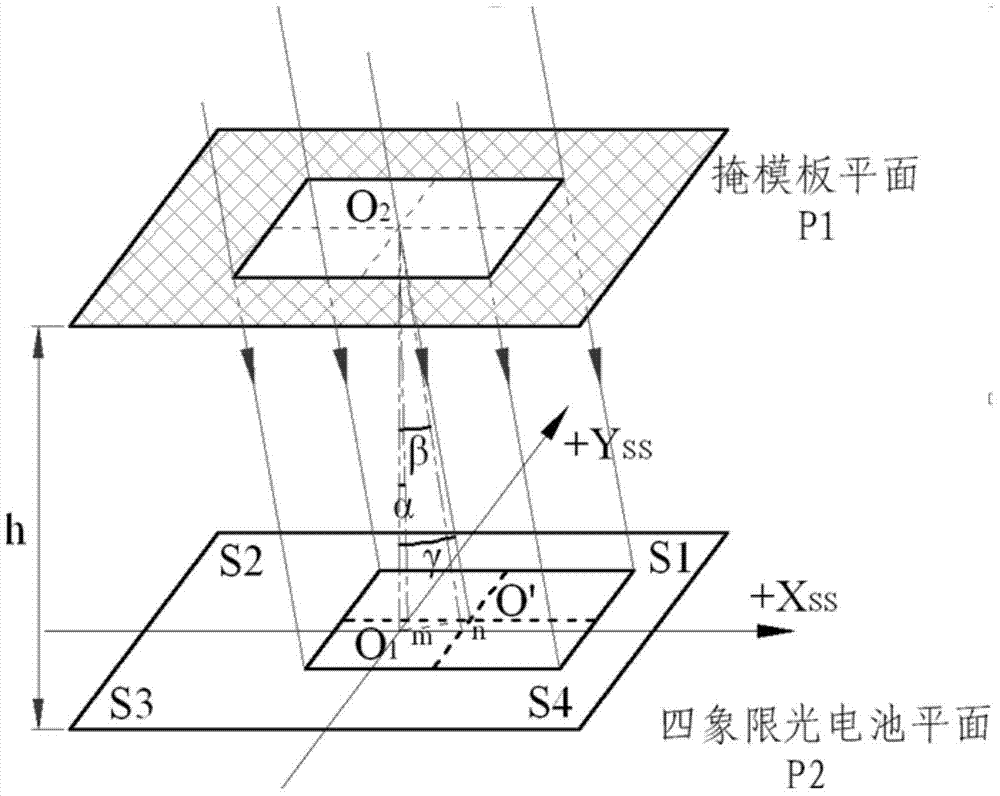
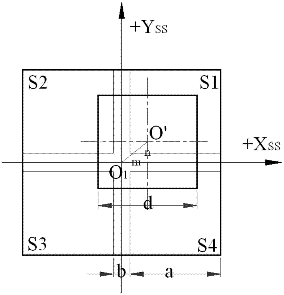
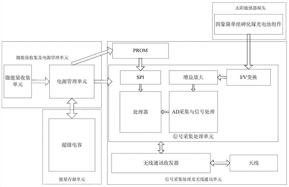
[0051] Provided is a solar sensor based on photovoltaic micro-energy collection applied to a satellite platform in a space environment, including a micro-energy collection and power management unit, a solar sensor probe, a signal acquisition and processing unit, a wireless communication unit, and an energy storage unit. The micro-energy collection and power management unit includes a micro-energy collection unit and a power management unit, and the solar sensor probe includes a four-quadrant single-junction gallium arsenide photovoltaic cell assembly and a photomask, and the signal acquisition and processing and wireless communication The unit includes a signal acquisition and processing unit, a wireless communication unit and a PROM program memory, and the working field of view of the sun sensor is 65 degrees x 65 degrees.

[0052] The micro-energy harvesting unit adopts a 3CM*4CM single-chip triple-junction gallium arsenide photovoltaic cell set on the outer surface of the su...


PUM


Abstract

The invention discloses a sun sensor based on collection of photovoltaic micro energy. The sun sensor comprises a micro energy collection and power supply management unit, a sun sensor probe, a signal acquisition processing and communication unit and an energy storage unit, wherein the micro energy collection and power supply management unit comprises a micro energy collection unit and a power supply management unit; the sun sensor probe comprises a four-quadrant type unijunction gallium arsenide photocell assembly and a light-pervious mask plate; the signal acquisition processing and communication unit comprises a signal acquisition processing unit, a communication unit and a PROM (programmable read-only memory).

Description

technical field [0001] The invention relates to an optical attitude sensor used in a satellite control subsystem, in particular to a solar sensor for wireless transmission based on photovoltaic micro-energy collection. Background technique [0002] The photosensitive unit of the existing analog sun sensor used in the space environment generally uses silicon photocell components, but when a single substrate cell is used to lithographically output multi-channel current signals, the current is a negative current, so the acquisition circuit needs to be equipped with a negative power supply , which increases the power supply burden and is not convenient for improving product integration. Moreover, due to the wide range of temperature changes in the space environment, the operating temperature range of traditional material photovoltaic modules such as silicon photovoltaic cells is narrow, and they cannot meet the requirements of long-term stable work under large temperature differ...

Claims


Application Information

Patent Timeline
Patent Type & Authority Patents(China)
IPC IPC(8): G01C21/02H02J7/35
CPCG01C21/02H02J7/345H02J7/35Y02E10/56
Inventor 梁鹤吕政欣盖芳钦陈然王春宇徐晓丹
Owner BEIJING INST OF CONTROL ENG
Why Eureka
Try Eureka