
Stabilizing apparatus and stabilizing method for linear polarization laser polarization and power

A technology for stabilizing devices and laser power, which is applied in the field of optical polarization multiplex transmission, can solve the problems of high incident angle and spot of laser, small aperture of acousto-optic modulator, complex and cumbersome adjustment, etc., so that no mechanical rotation, Simple structure, stable polarization and power at the same time

Inactive Publication Date: 2016-03-30
NAT TIME SERVICE CENT CHINESE ACAD OF SCI
View PDF6 Cites 11 Cited by
  • Summary
  • Abstract
  • Description
  • Claims
  • Application Information

AI Technical Summary

Problems solved by technology

Due to the small aperture of the acousto-optic modulator, the requirements for the incident angle and spot of the laser are relatively high, the adjustment is complicated and cumbersome, and the power loss is large

Method used


Image

  • Stabilizing apparatus and stabilizing method for linear polarization laser polarization and power
  • Stabilizing apparatus and stabilizing method for linear polarization laser polarization and power

Examples


Embodiment 1

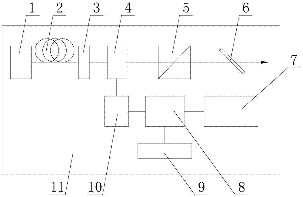
[0022] exist figure 1 Among them, the linearly polarized laser polarization and power stabilizing device of this embodiment consists of a grating feedback semiconductor laser 1, a single-mode polarization-maintaining fiber 2, a λ / 2 wave plate 3, a liquid crystal variable phase retarder 4, a polarization beam splitter prism 5, a non- Polarization beam splitting lens 6, laser power detector 7, servo controller 8, oscilloscope 9, signal source 10, and mounting plate 11 are connected to form.

[0023] On the mounting plate 11, a grating feedback semiconductor laser 1 is fixedly connected and installed with a threaded fastening connector. The grating feedback semiconductor laser 1 provides a laser source for the present invention. The laser wavelength emitted by the grating feedback semiconductor laser 1 is 679nm, and the laser emits a horizontal optical axis. The single-mode polarization-maintaining optical fiber 2 is fixedly installed on the mounting plate 11 in the direction of ...

Embodiment 2

[0034] The laser wavelength emitted by the grating feedback semiconductor laser 1 in this embodiment is 670nm, the wavelength of the λ / 2 wave plate 3 is 670nm, and other components and the connection relationship between the components are the same as in the first embodiment.

Embodiment 3

[0036] The laser wavelength emitted by the grating feedback semiconductor laser 1 of this embodiment is 700nm, the wavelength of the λ / 2 wave plate 3 is 700nm, and the other components and the connection relationship between the components are the same as in the first embodiment.


PUM


Abstract

A stabilizing apparatus and a stabilizing method for linear polarization laser polarization and power are disclosed. After laser passes through a liquid crystal variable phase delayer, the laser is subjected to polarization and filtration through a polarizing beam splitter prism; polarization fluctuation is converted into power fluctuation; then power fluctuation sampling is performed by an unpolarized splitting lens, and the sampled power fluctuation is compared with a standard voltage signal to obtain a power fluctuation error signal; the voltage amplitude of a square wave signal loaded on the liquid crystal variable phase delayer is regulated; the phase retardation characteristic of the laser between two cross-polarization components in the laser can be changed; and the error signal passes through a servo controller and then is fed back to the liquid crystal variable phase delayer for performing closed loop locking so as to realize the stabilization for the linear polarization laser polarization and power concurrently. The stabilizing apparatus has the advantages of reasonable design, simple structure, easy regulation, relatively less insertion loss, free of mechanical rotation and the like; real-time continuous and wide-range laser power regulation can be realized; high accuracy stabilization for the laser polarization and power is achieved; and the stabilizing apparatus and the stabilizing method can be applied to space laser power stabilizing experiment apparatuses.

Description

technical field [0001] The invention belongs to the technical field of optical polarization multiplex transmission, and specifically relates to a device for stabilizing the polarization and power of linearly polarized laser light by using a liquid crystal variable phase retarder and a method for stabilizing the polarization and power of linearly polarized laser light. Background technique [0002] At present, optical laboratories generally use optical fibers to transmit laser light in space. If there is a requirement for certain polarization of laser light, single-mode polarization-maintaining optical fibers are generally used. However, due to environmental temperature and humidity changes, mechanical vibration and air flow and other factors , the polarization and power of the laser passing through the single-mode polarization-maintaining fiber will have some fluctuations. If the polarization beam splitting prism is used to split the light, the original polarization fluctuati...

Claims


Application Information

Patent Timeline
Patent Type & Authority Applications(China)
IPC IPC(8): H01S5/0687H01S5/0683
CPCH01S5/0687H01S5/06837
Inventor 王叶兵孔德欢常宏
Owner NAT TIME SERVICE CENT CHINESE ACAD OF SCI
Learn More