Millimeter wave tile-type phased-array antenna TR module

A phased array antenna and wave tile-type technology, which is applied to antennas, antenna arrays, antenna supports/mounting devices, etc., can solve problems such as low integration, difficulty, and uncertainty, and achieve high heat dissipation efficiency and heat dissipation paths The effect of short and small thermal resistance

Active Publication Date: 2016-04-20
10TH RES INST OF CETC
View PDF8 Cites 54 Cited by
  • Summary
  • Abstract
  • Description
  • Claims
  • Application Information

AI Technical Summary

Problems solved by technology

It is very difficult to realize, and the precision is difficult to control
[0005] The currently reported tile-type TR components generally use elastic connectors such as FuzzButton as the external interface. This kind of RF vertical interconnection is easy to use, but it is difficult to achieve component airtightness.
Some tile-type TR components adopt the RF vertical interconnection of the waveguide interface, which has a low integration level and is inconvenient to connect between modules. This solution is not used at present.
IMST of Germany proposed a method of integrated integration of TR components and antenna array. The chip and antenna patch are respectively located on both sides of an LTCC integrated with liquid-cooled microchannels. This solution has a high degree of integration, but the heat dissipation efficiency is relatively low Low, it is difficult to work reliably for a long time for applications with a transmission power of more than hundreds of mW
Moreover, since the liquid-cooling channel must be integrated in this

Method used


Image

  • Millimeter wave tile-type phased-array antenna TR module
  • Millimeter wave tile-type phased-array antenna TR module
  • Millimeter wave tile-type phased-array antenna TR module

Examples


Embodiment Construction

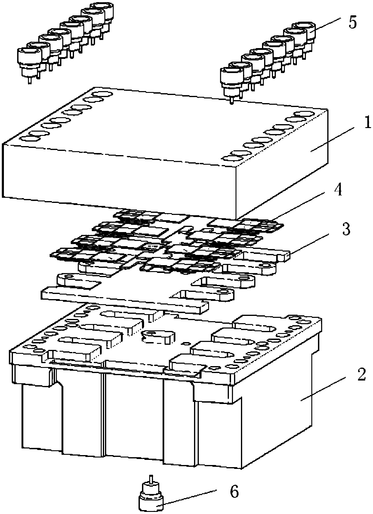
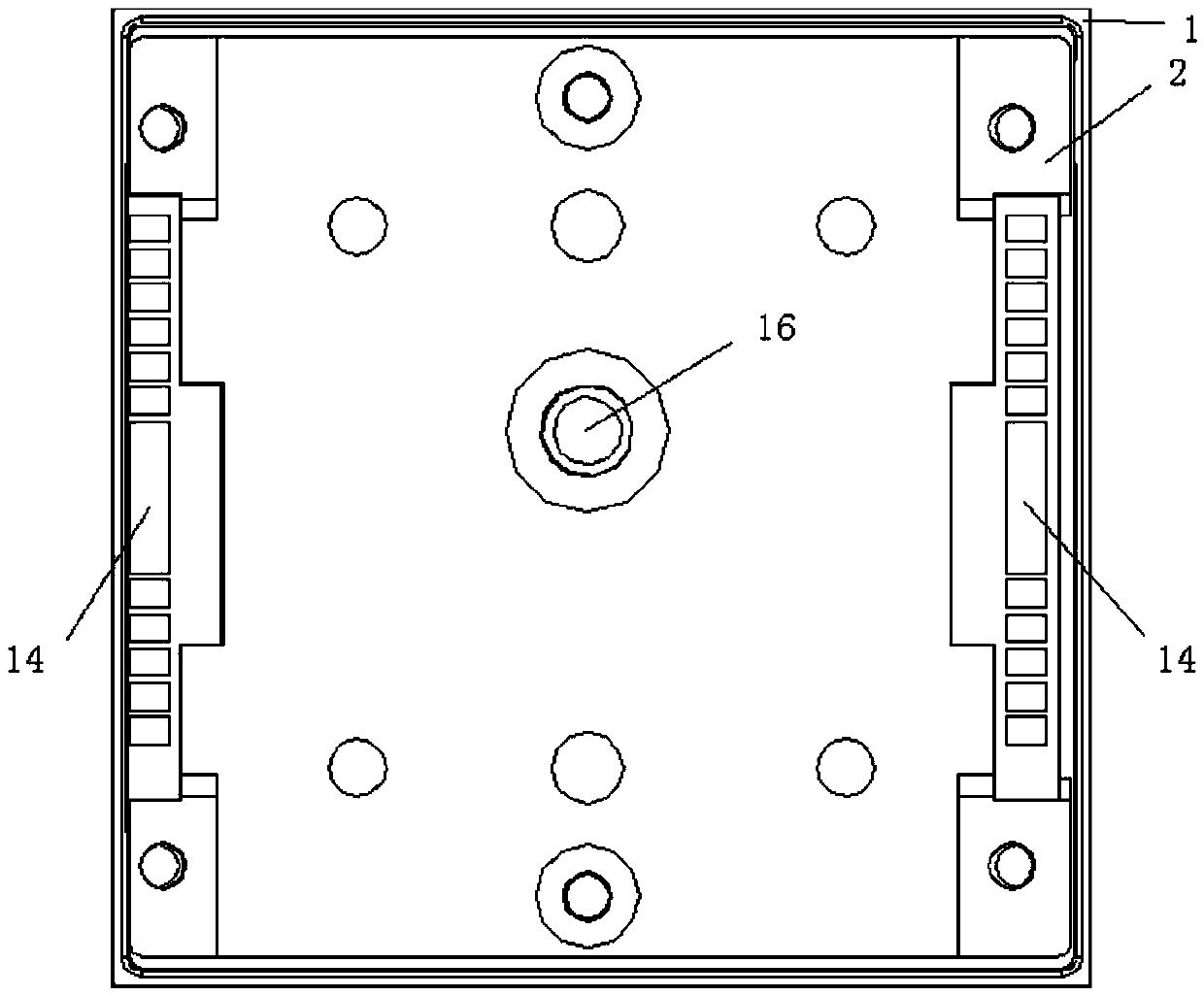
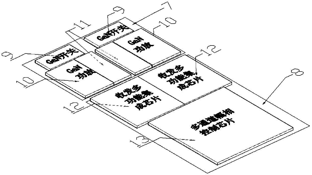
[0027] refer to Figure 1-Figure 5 . In the embodiment described below, a millimeter-wave tile-type phased array antenna TR component operates at the millimeter-wave frequency band, and the working mode is half-duplex transmission and reception. The single-channel transmission power is at the watt level. Cloth tile TR assembly, made of 2 N An upper chamber 1 of the TR assembly with an antenna radio frequency vertical interconnection interface 5, and a lower chamber 2 of the TR assembly with a common radio frequency vertical interconnection interface 6 at the bottom, located between the upper and lower chambers of the above-mentioned TR assembly, and connected to the lower chamber A multi-layer circuit board 3 and a chipset 4 integrated by body welding, characterized in that: 2 N All the chips and the power distribution network of each transceiver channel are integrated in a TR module sub-array with high density; all the channels are divided into two parts and symmetrically a...


PUM


Abstract

The invention relates to a millimeter wave tile-type phased-array antenna TR module, and the invention aims at providing a TR module realization scheme with advantages of high reliability, low cost and high density integration for a millimeter wave frequency range high-power active phased-array antenna (APAA). The millimeter wave tile-type phased-array antenna TR module can be realized by the following scheme: a radio-frequency signal is fed from a radio-frequency vertical interconnection interface of a common port of the lower cavity bottom of the TR module, after the radio-frequency signal is performed the power distribution through a power divider mounting on the surface of a multi-layer circuit board and the like, the radio-frequency signal is fed in a multichannel amplitude-phase control chip connected with every transmit-receive channel, after the radio-frequency signal is performed the second power distribution by the multichannel amplitude-phase control chip, the amplitude-phase information of each channel radio-frequency signal is adjusted according to the state of the external control code and is outputted to a TR multi-function chip, the signal is amplified and outputted to the final power amplifier until saturation, the signal is outputted to a power switch, the emission access is gated, and the signal is transmitted to antenna radio-frequency vertical interconnection interfaces arranged on two ends of the cavity on the TR module; when the TR module receives a work, the radio-frequency signal passes through the TR module in a reverse direction.

Description

technical field [0001] The invention relates to a tile-type phased array antenna TR assembly, in particular to an active phased array antenna TR assembly of a transceiver half-duplex system working in the millimeter wave frequency band and a high-power millimeter wave tile with a single channel transmission power up to watt level Type TR component implementation technology. Background technique [0002] At present, the two-dimensional active phased array antennas widely used mostly use brick structure TR components, which are characterized in that the component placement direction is perpendicular to the aperture of the phased array antenna, and the circuit adopts vertical integration and transverse assembly (LITA). Not limited to half-wavelength and can be extended according to design requirements. Therefore, this structure has low integration, relatively low design difficulty, high technology maturity, and easy circuit design and assembly; however, this structure limits t...

Claims


Application Information

Patent Timeline
IPC IPC(8): H01Q1/12H01Q21/00
CPCH01Q1/12H01Q21/00H01Q21/0025
Inventor 赵青黄建罗鑫
Owner 10TH RES INST OF CETC
Why Eureka
Try Eureka