Check patentability & draft patents in minutes with Patsnap Eureka AI!

Sulfur-tolerant shift catalyst circulating vulcanization process

A catalyst cycle and sulfur-resistant shift technology, which is applied in the coal chemical industry to achieve the effects of increasing the cyclic sulfurization rate, increasing the inlet temperature and reducing the consumption of raw materials

Inactive Publication Date: 2016-06-08
CONNELL CHEM IND
View PDF4 Cites 4 Cited by
  • Summary
  • Abstract
  • Description
  • Claims
  • Application Information

AI Technical Summary

Problems solved by technology

[0011] The technical problem to be solved by the present invention is to substantially improve the deficiencies in the existing technology, and provide a sulfur-resistant shift catalyst cyclic vulcanization process. This process has the advantages of safe and reliable vulcanization operation, low consumption of chemical raw materials, and cyclic vulcanization , high-sulfur gas recovery and utilization, hydrogen sulfide gas after sulfide conversion into elemental sulfur recovery, no environmental pollution, etc., focusing on solving the problem of environmental pollution caused by high-sulfur gas emissions

Method used


Image

  • Sulfur-tolerant shift catalyst circulating vulcanization process
  • Sulfur-tolerant shift catalyst circulating vulcanization process
  • Sulfur-tolerant shift catalyst circulating vulcanization process

Examples


Embodiment 2

[0072] Embodiment 2, the technological process of present embodiment and embodiment 1 is exactly the same, and difference is that process parameter is different, and details are as follows:

[0073] 1) Heating process:

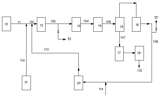
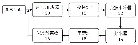
[0074] a) Nitrogen gas 116 delivered from the outside at a pressure of 3.0 MPa is heated by the start-up heater 20 and then sent to the shift furnace 12 to heat up the sulfur-resistant catalyst in the shift furnace 12, and the shift gas generated after the temperature rise enters the shift water cooler 13 After the temperature drops to 30-45°C, it enters the water separator 14, and the mixed gas 105 separated from the condensed liquid by the water separator 14 enters the methanol wash 15 for acid gas separation, and then the cryogenic separator 16 separates the It is sent to the start-up heater 20 for recycling, and after the temperature of the catalyst bed in the shift furnace 12 reaches 220° C., the delivery of nitrogen is stopped;

[0075] b) Close the val...

Embodiment 3

[0097] Embodiment 3, the technological process of present embodiment and embodiment 1 and embodiment 2 is identical, and difference is that process parameter is different, and details are as follows:

[0098] 1) Heating process:

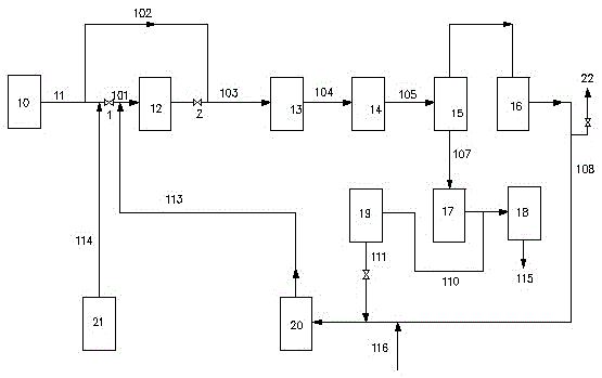
[0099] a) Nitrogen gas 116 delivered from the outside at a pressure of 3.0 MPa is heated by the start-up heater 20 and then sent to the shift furnace 12 to heat up the sulfur-resistant catalyst in the shift furnace 12, and the shift gas generated after the temperature rise enters the shift water cooler 13 After the temperature drops to 30-45°C, it enters the water separator 14, and the mixed gas 105 separated from the condensed liquid by the water separator 14 enters the methanol wash 15 for acid gas separation, and then the cryogenic separator 16 separates the It is sent to the start-up heater 20 for recycling, and after the temperature of the catalyst bed in the shift furnace 12 reaches 220° C., the delivery of nitrogen is stopped;

[0100] b) Clo...


PUM


Abstract

The invention relates to a sulfur-tolerant shift catalyst circulating vulcanization process. The sulfur-tolerant shift catalyst circulating vulcanization process is characterized by comprising the following steps that heating is conducted on a shift converter (12) through nitrogen (116); fresh water gas (11) enters an outlet of the shift converter (12), shift gas produced by the shift converter is mixed with the fresh water gas to enter a methanol wash device (15), separated flashing steam (107) enters a hydrogen sulfide recovery tower (17), and recovered hydrogen sulfide (110) enters a hydrogen sulfide compressor (19) to be pressurized and sent to a starting heater (20) to be mixed with liquid carbon disulfide (114) at a shift converter inlet (101); the fresh water gas (11) is conveyed into the shift converter inlet (101) and replenished to the outlet of the shift converter (12); the temperature of the shift converter (12) rises, and the liquid carbon disulfide (114) is added to conduct a vulcanization reaction; reacted shift gas is mixed with the replenished fresh water gas (11) to enter the methanol wash device (15), the separated flashing steam (107) enters the hydrogen sulfide recovery tower (17), the recovered hydrogen sulfide (110) enters the hydrogen sulfide compressor (19) to be pressurized and sent to the starting heater (20) to be mixed with the liquid carbon disulfide (114) at the shift converter inlet (101), and vulcanization reinforcement is conducted; the processes of cooling, sulfur discharging and sulfur recovery are conducted.

Description

technical field [0001] The invention relates to the technical field of coal chemical industry, and relates to a cycle vulcanization process of a sulfur-resistant shift catalyst. Background technique [0002] At present, in domestic coal chemical production, the shift system usually uses cobalt-molybdenum series sulfur-tolerant shift catalysts, which are oxidized cobalt oxide CoO and molybdenum oxide MoO before use. 3 , the activity is poor, and it needs to be vulcanized into cobalt sulfide CoS and molybdenum sulfide MoS 2 , in order to increase its activity. There is one kind of sulfur-resistant shift catalyst vulcanization process in the more advanced prior art: namely figure 1 The cyclic vulcanization process shown in this process uses water gas or semi-water gas with a hydrogen content of more than 25% as a carrier. When the temperature of the catalyst bed rises to 200-230°C, liquid carbon disulfide 114 is added to the inlet 101 of the converter. , the liquid carbon di...

Claims


Application Information

Patent Timeline
IPC IPC(8): B01J37/20
CPCB01J37/20
Inventor 常文志韩庆茹张则雪金管会
Owner CONNELL CHEM IND
Features
  • R&D
  • Intellectual Property
  • Life Sciences
  • Materials
  • Tech Scout
  • Unparalleled Data Quality
  • Higher Quality Content
  • 60% Fewer Hallucinations
Learn More