Router structure based on microring resonators and arrayed waveguide grating

A technology of arrayed waveguide gratings and microring resonators, applied in the field of data transmission, can solve the problems of large packet delay and restricting the performance of optical switch architectures in data centers, and achieve the effects of improving performance, reducing switching time, and breaking through delay bottlenecks

Active Publication Date: 2016-06-08
XIDIAN UNIV
View PDF6 Cites 3 Cited by
  • Summary
  • Abstract
  • Description
  • Claims
  • Application Information

AI Technical Summary

Problems solved by technology

[0007] To achieve optical packet switching, the entire decision-making process, including label extraction, photoelectric conversion, decision processing, and control information distribution, must be completed in a very short period of time. Therefore, the centralized control meth

Method used


Image

  • Router structure based on microring resonators and arrayed waveguide grating
  • Router structure based on microring resonators and arrayed waveguide grating
  • Router structure based on microring resonators and arrayed waveguide grating

Examples


Embodiment Construction

[0029] The present invention will be described in further detail below in conjunction with the accompanying drawings.

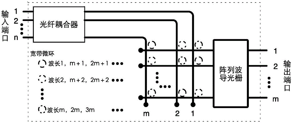
[0030] see figure 2 , the present invention structurally includes a fiber coupler 1 and an arrayed waveguide grating 2 . The input port of the fiber coupler 1 is connected to n input fibers, 1-n is the label of the fiber, the output port of the fiber coupler 1 is connected to m output fibers, the input port of the arrayed waveguide grating 2 is connected to m input fibers, and the m The input optical fibers and the m output optical fibers of the fiber coupler 1 are crossed, and the two are not in contact with each other. A microring resonator 3 with different coupling frequencies is arranged at the crossing position of the optical fiber, and the microring resonator 3 is connected to the crossing position. The two fibers touch each other. The microring resonator 3 is arranged behind the output fiber of the fiber coupler 1 and above the input fiber of the ar...


PUM


Abstract

The invention relates to a router structure based on microring resonators and an arrayed waveguide grating. The router structure comprises an optical fiber coupler and an arrayed waveguide grating, wherein the input port of the optical fiber coupler is connected with n input optical fibers, and the output port of the optical fiber coupler is connected with m output optical fibers; the input port of the arrayed waveguide grating is connected with m input optical fibers; the m input optical fibers and the m output optical fibers of the optical fiber coupler are arranged in a crossed manner without contacting, microring resonators having different coupling frequencies are arranged at the crossed positions of the optical fibers, and the microring resonators are in contact with two optical fibers at the crossed position; the output port of the arrayed waveguide grating is connected with m output optical fibers; and m and n are positive integers. According to the router structure based on the microring resonators and the arrayed waveguide grating, the exchange time is reduced, the bottleneck of time delay which is the most important to optical packet switching is broken through, the performances of the whole system are improved, and communication between any one input port and any one output port is realized.

Description

technical field [0001] The invention relates to the field of data transmission, in particular to a router structure based on a microring resonator and an arrayed waveguide grating. Background technique [0002] Cloud computing and the emergence of a large number of Internet applications have led to the explosive growth of data center network traffic, so the data center network needs to be supported by switches with high bandwidth. However, the traditional data center network based on electrical packet switches has a sharp increase in energy consumption due to the increase in traffic. At the same time, the rate of traditional electrical packet switches is limited by the bottleneck of existing technology development, so it cannot meet the performance requirements of the data center. Therefore, due to its high throughput, low latency, and low energy consumption, the optical network has been widely concerned in the application of data centers, and the core part of the data cente...

Claims


Application Information

Patent Timeline
IPC IPC(8): G02B6/12
CPCG02B6/12009
Inventor 顾华玺王曦余晓杉王琨杨银堂
Owner XIDIAN UNIV
Why Eureka
Try Eureka