Absorption Type-Removal/Condensing Apparatus

A concentration device and absorption technology, which is applied in the field of absorption removal and concentration devices, can solve the problems of impossibility, deterioration, expensive energy consumption, etc., and achieve the effects of preventing the air supply from being too dry, reducing energy loss, and avoiding insufficient separation

Active Publication Date: 2016-06-29
SEIBU GIKEN CO LTD
View PDF6 Cites 15 Cited by
  • Summary
  • Abstract
  • Description
  • Claims
  • Application Information

AI Technical Summary

Problems solved by technology

[0024] However, it is described in Patent Documents 1 and 2 that, for example, if it is intended to use a general zeolite as an adsorbent for carbon dioxide and separate carbon dioxide by displacement desorption with water, the water will be adsorbed in the pores of the zeolite, and the carbon dioxide of the zeolite will The adsorption capacity will be significantly reduced, and as a result, the substance recovery rate η of the device (that is, the efficiency of separating and removing the target substance from the treatment target air by adsorption in the treatment area) will be significantly reduced, so heating and humidification cannot be performed. run
[0025] In addition, even if an aqueous solution of amine is used, regeneration requires a high temperature of, for example, 120°C and a large amount of energy is required.
In addition, regeneration at high temperature also causes problems of deterioration or odor
[0026] If instead of zeolite, an amine-loaded solid absorbent is used as the carbon dioxide absorbent, and water vapor is used as the regeneration gas for ventilation in the regeneration zone, the carbon dioxide desorption and humidity given by the amine-loaded solid absorbent will be obtained. effect, but requires boiler equipment, making it an expensive and energy-intensive device

Method used


Image

  • Absorption Type-Removal/Condensing Apparatus
  • Absorption Type-Removal/Condensing Apparatus
  • Absorption Type-Removal/Condensing Apparatus

Examples


Embodiment 1

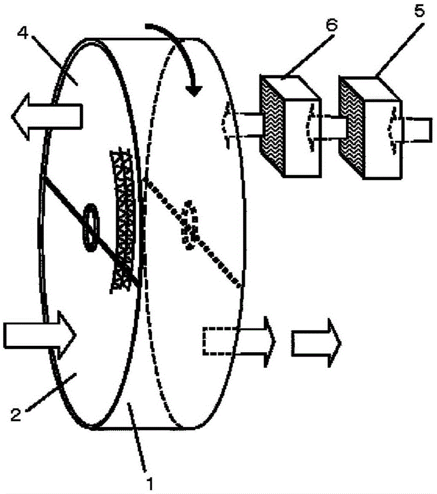
[0057] Below, based on figure 1 Embodiments of the absorption type removal and separation apparatus of the present invention will be described in detail. 1 is a honeycomb rotor, which is processed by processing non-combustible sheets such as ceramic fiber paper into cell stripes (with waves) and wound into a rotor shape, loaded with potassium carbonate (potassium bicarbonate), carbonic acid Inorganic absorbents such as sodium (sodium bicarbonate), organic absorbents such as triethylethanolamine and monoethanolamine, or weakly basic ion exchange resins.

[0058] The honeycomb rotor 1 is divided into a treatment zone 2 and a regeneration zone 4 . In the processing area 2, indoor air is supplied by a fan etc. (it is a normal fan, so it is not shown in figure).

[0059] The air to be treated is ventilated in the treatment area 2, and the carbon dioxide contained in the air to be treated is absorbed by the absorbent in the rotor part and separated and removed from the air to be t...

Embodiment 2

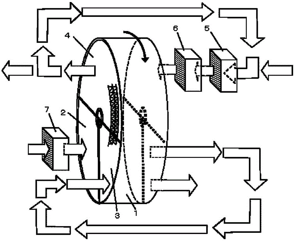
[0062] Such as figure 2 As shown, the honeycomb rotor 1 is divided into a treatment area 2 , a treatment area 3 and a regeneration area 4 . In the processing area 2, indoor air is supplied by a fan etc. (it is a normal fan, so it is not shown in figure).

[0063] The air to be treated passes through the humidifying unit 7 for treatment, and is ventilated in the treatment area 2, so that the carbon dioxide contained in the air to be treated is absorbed by the absorbent in the rotor portion and separated from the air to be treated. Then, a part or all of the treated outlet air is passed through the treatment zone 3 to remove carbon dioxide, thereby reducing the concentration of carbon dioxide.

[0064] In the regeneration zone 4, the used regeneration air that has passed through the regeneration zone 4 is mixed with the outside air, and the regeneration air heated by the heater 5 is ventilated in the regeneration humidification unit 6, so that the absorbed carbon dioxide is us...

Embodiment 3

[0066] Such as image 3 As shown, the enthalpy is recovered and the regeneration energy is reduced by making the regeneration outlet air and the external air of Example 2 pass through different flow paths of the total heat exchanger 8 respectively. Not only the second embodiment but also other embodiments can combine the total heat exchanger to exchange heat between the regeneration outlet air with high enthalpy and the external air for regeneration, so as to achieve the energy saving effect.

[0067] The above is the description of the structure of the absorption type removal and concentration device. Taking the embodiment 2 as an example, the operation will be described while adding air conditions. first, Figure 4 The example shown is an example of comparing the concentration of carbon dioxide at the outlet of the regeneration zone when the absolute humidity of the low-temperature regeneration air (55°C) is 4 to 30 g / kg' (carbon dioxide concentration: 450 ppm). The condit...


PUM


Abstract

The invention provides an absorption type-removal / condensing apparatus for removing or condensing carbon dioxide with high recovery efficiency comprises: a honeycomb rotor which has an absorption function of carbon dioxide as an amine support solid absorbent, said honeycomb rotor being divided into a processing zone and a reproduction zone at least, carbon dioxide being removed from subject air to be processed by making a maintenance absorbent of a rotor portion absorb the carbon dioxide contained in the air to be processed by ventilating the subject air to be processed through said processing zone, and the carbon dioxide absorbed in said processing zone by the maintenance absorbent being made to be contained into the air to be reproduction by ventilating the air to be reproduced through said reproduction zone to reproduce the maintenance absorbent of said rotor portion, wherein said apparatus has a humidity adjustment device which makes high a relative humidity of any of the air to be reproduced ventilated through said reproduction zone and the air to be processed ventilated through the processing zone or both, so that absorbing performance and condensing performance are improved.

Description

technical field [0001] The present invention relates to the separation of carbon dioxide contained in the air to be treated from the air to be treated by using, for example, a honeycomb rotor (honeycombrotor) holding a carbon dioxide gas absorbent such as potassium carbonate, an amine-added porous material, and a weakly basic ion-exchange resin. Absorption removal and concentration devices that can remove and concentrate carbon dioxide according to different purposes, such as for the purpose of removing carbon dioxide in buildings, etc., or for the purpose of supplying concentrated high-concentration carbon dioxide to plastic greenhouses or plant factories, etc. . Background technique [0002] In the prior art, as a device capable of separating and removing a gaseous substance to be removed from the air to be treated in a concentrated state at a low temperature, for example, as described in Patent Documents 1 and 2, there are known suction-loading and detachable concentrator...

Claims


Application Information

Patent Timeline
Patent Type & Authority Applications(China)
IPC IPC(8): B01D53/06
CPCB01D53/06B01D2257/406B01D2257/504B01D2257/708B01D2259/40086B01D2251/304B01D2251/306B01D2251/606B01D2252/20484B01D2252/20489B01D2253/112B01D2253/206B01D2253/25B01D2253/3425B01D2257/302B01D2257/404B01D2257/90B01D2258/06B01D2259/4009B01D2259/4508B01D53/62Y02A50/20Y02C20/40
Inventor 丸山香名江井上宏志冈野浩志黑田彩子
Owner SEIBU GIKEN CO LTD
Why Eureka
Try Eureka