Silicon carbon composite material, fabrication method thereof, anode material and battery

A silicon-carbon composite material and silicon material technology, applied in battery electrodes, circuits, electrical components, etc., can solve the problems of difficult preparation process and poor interface contact, and achieve the effects of easy process control, improved utilization rate, and large production capacity.

Active Publication Date: 2016-07-06
SUZHOU GCLSI SCI & TECH IND APPL RES INST CO LTD +3
View PDF6 Cites 23 Cited by
  • Summary
  • Abstract
  • Description
  • Claims
  • Application Information

AI Technical Summary

Problems solved by technology

[0006] Based on this, it is necessary to provide a silicon-carbon composite material with good interface contact and simple preparation for the problems of poor interface contact between silicon material and carbon material in the existing silicon-carbon composite materials and difficult preparation process. Material

Method used


Image

  • Silicon carbon composite material, fabrication method thereof, anode material and battery

Examples


preparation example Construction

[0039] A method for preparing a silicon-carbon composite material, comprising the steps of:

[0040] S1. Disperse the metal organic compound in the first dispersion medium, add silicon material and mix evenly, and then spray dry to obtain the first precursor;

[0041] S2. Calcining the first precursor at 350-1000° C. in a gas atmosphere to obtain nanoparticles;

[0042] S3, uniformly mixing the nanoparticles and the binder, gradually adding carbon materials, and ultrasonically dispersing to obtain the second precursor;

[0043] S4. Sintering the second precursor at 300-900° C. to obtain a silicon-carbon composite material.

[0044] In S1, metal-organic compounds refer to compounds formed by direct bonding of carbon atoms and metal atoms, and the bonding forms can be covalent bonds, ionic bonds, coordination bonds, etc. The metal organic compound is the metal source of the metal compound in the nanoparticle, and the metal organic compound is selected according to the metal co...

Embodiment 1

[0065] A metal organic compound (trimethylaluminum, 8.5 g) was dispersed in hexane, then a silicon material (silicon powder, 10 nm, 200 g) was added, and stirred for 1 h to obtain a slurry. Then the slurry was input into a spray dryer, and dried at 100° C. to obtain the first precursor.

[0066] The first precursor is fed into a continuous reaction furnace and calcined at 500° C. for 9.5 hours under an oxygen atmosphere; nanoparticles are obtained.

[0067] Disperse the nanoparticles and the binder polyvinylidene fluoride PVDF in N-methylpyrrolidone NMP, then disperse the carbon material (carbon nanotubes, 10 g) in hexane, and stir for 1 h. Then dry at 110° C. for 3 h to obtain the second precursor.

[0068] The second precursor was sent into a continuous reaction furnace for sintering at 750 °C for 11.5 h.

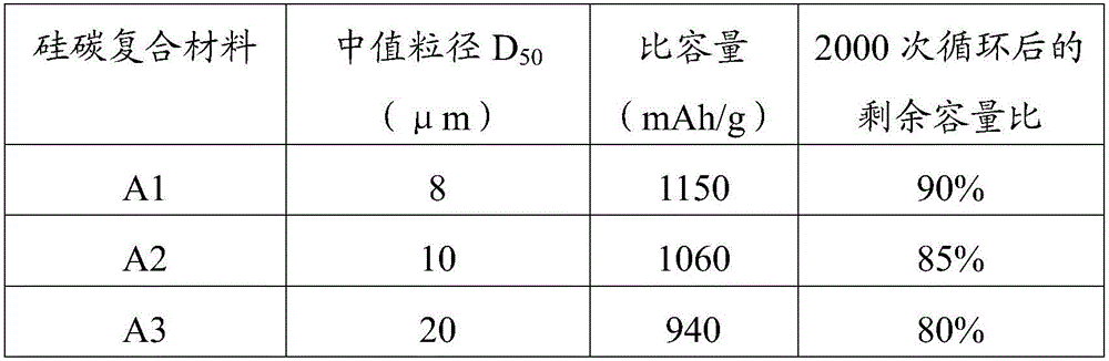
[0069] The obtained silicon-carbon composite material is denoted as A1.

Embodiment 2

[0071] The second embodiment is basically the same as the first embodiment, except that the silicon material (SiO 2 , 200 nanometers, 150g), metal-organic compound (dimethylmagnesocene, 5.6g), carbon material (graphene, 8g); other parts are the same as in Example 1.

[0072] The obtained silicon-carbon composite material is denoted as A2.


PUM

PropertyMeasurementUnit
particle sizeaaaaaaaaaa

Abstract

The invention relates to a silicon carbon composite material. The silicon carbon composite material comprises a three-layer core-shell structure, wherein a silicon material is arranged at the innermost layer, a metal compound is arranged at the intermediate layer, a carbon material is arranged at the outermost layer, and the silicon material is selected form one or more of silicon, a silicon oxide and a metal silicide. In the above silicon carbon composite material, the intermediate layer of the metal compound is further arranged between the silicon material and the carbon material, the interface contact between the silicon material and the carbon material is effectively improved, so that the silicon carbon composite material is more stable during the application process. The conductivity of the silicon carbon composite material is improved, and the energy density is also improved. The silicon carbon composite material is easier to be bonded with a current collector during the subsequent preparation and application process, and is difficult to be agglomerated or drop, and the cycle performance of the silicon carbon composite material is improved. The fabrication method is low in process difficulty, the device is simple, and the industrial production is facilitated. The invention also discloses a fabrication method of the above silicon carbon composite material, an anode material and a battery.

Description

technical field [0001] The invention relates to the field of batteries, in particular to a silicon-carbon composite material, a preparation method thereof, a negative electrode material and a battery. Background technique [0002] Compared with traditional graphite anode materials, silicon has an ultra-high theoretical specific capacity (4200mAh / g) and a lower delithiation potential (<0.5V), and the voltage platform of silicon is slightly higher than that of graphite, which is not easy to charge when charging. The behavior of lithium precipitation on the surface occurs, and the safety performance is better, so it has become a new research direction for the negative electrode material of the battery. [0003] However, since silicon is a semiconductor material, when it is used as a battery negative electrode material, its own conductivity is low, and the insertion and extraction of lithium ions in the process of charging and discharging will cause the volume of silicon to e...

Claims


Application Information

Patent Timeline
Patent Type & Authority Applications(China)
IPC IPC(8): H01M4/36H01M4/38H01M4/485H01M4/58H01M4/587
CPCH01M4/366H01M4/386H01M4/485H01M4/58H01M4/582H01M4/587Y02E60/10
Inventor 郝三存胡磊樊仁义
Owner SUZHOU GCLSI SCI & TECH IND APPL RES INST CO LTD
Why Eureka
Try Eureka