

Reinforced desorption method of acidic gas
A technology for desorption of acidic gases, applied in chemical instruments and methods, separation methods, air quality improvement, etc., can solve the problems of inability to strengthen the desorption process of the absorption liquid, and achieve the effects of reduced energy consumption, easy control, and efficient removal
- Summary
- Abstract
- Description
- Claims
- Application Information
AI Technical Summary
Problems solved by technology
Method used
Image

Examples
Embodiment 1
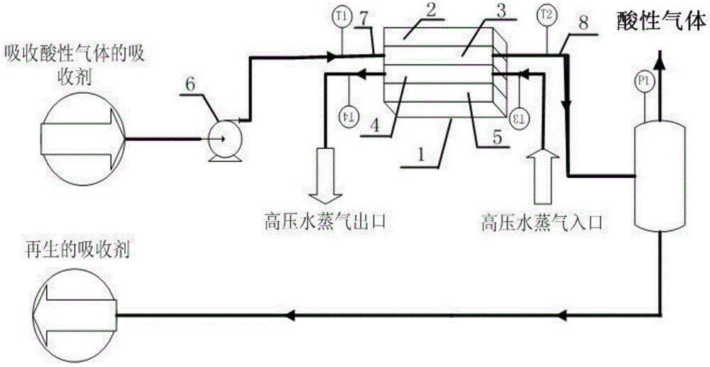
[0036] Example 1: Regeneration of CO 2 Absorbent Diethanolamine (DEA)
[0037] Under the condition of system pressurization (P1, 0.1 ~ 1MPa), from the absorption of CO 2 Diethanolamine (DEA) aqueous solution (temperature T1, CO 2 / DEA mol ratio 0.32, absorbing liquid concentration 30% DEA) is transported into inner groove type microchannel reactor desorption unit 3 by pump 6, passes into high-pressure water vapor (T3 in inner groove type microchannel reactor heat exchange unit 4) , 100~180℃) to heat the inner groove type microchannel reactor 1, so that the temperature of the absorption liquid rises to the desorption temperature (T4, 90~160℃), and the carbon dioxide from the absorption liquid is completed in the microchannel of the inner groove structure. In the desorption, and at the outlet to form a desorption liquid and carbon dioxide mixed two-phase material. It has been determined that under the conditions of system pressure 0.1MPa, residence time 0.01 seconds, and deso...
example 2
[0039] Example 2: Regeneration of CO 2 Absorbent N-methyldiethanolamine (MDEA)
[0040] to absorb CO 2 MDEA (CO 2 / MDEA=0.40, absorbing solution concentration 40% MDEA) is the liquid to be desorbed, desorbed in the internal groove type microreactor described in example 1 and method. It has been determined that under the conditions of system pressure of 1MPa, residence time of 100 seconds, and desorption temperature of 90-160°C, CO 2 The precipitation rate is 40% to 100%.
example 3
[0041] Example 3: Regeneration of CO 2 Composite absorption liquid methyldiethanolamine MDEA / piperazine PZ
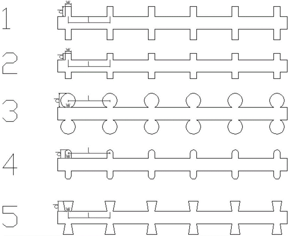
[0042] to absorb CO 2 MDEA / PZ (CO 2 / MDEA=0.45, absorbing liquid concentration 35% MDEA+3%PZ) is the liquid to be desorbed, desorbed in the method described in example 1. The width w of the inner groove structure is 50 microns, the depth d is 500 microns, and the height is 1000 microns. The distance l between two adjacent inner groove structures is 5 mm. The channel equivalent diameter is 750 microns, and the channel shape is rectangular. It has been determined that under the conditions of system pressure of 0.5MPa, residence time of 1 second, and desorption temperature of 90-160°C, CO 2 The precipitation rate is 50% to 100%.
[0043] It should be noted that the method for acid gas enhanced desorption in the present invention can change the temperature, flow rate and residence time in the inner groove type microchannel reactor according to actual conditions, such a...
PUM
| Property | Measurement | Unit |
|---|---|---|
| Diameter | aaaaa | aaaaa |
| Width | aaaaa | aaaaa |
| Depth | aaaaa | aaaaa |
Abstract
Description
Claims
Application Information