Electrode plate and lithium ion battery

A technology of electrode sheet and conductive layer, applied in battery electrodes, secondary batteries, non-aqueous electrolyte battery electrodes, etc., can solve the problems of electrode structure damage capacity, loss of electron and ion channels, hidden dangers of battery safety, etc., and achieve good stability and interfacial contact properties, high gram capacity and energy density, avoidance of adverse effects

Inactive Publication Date: 2016-07-20
CHANGCHUN INST OF APPLIED CHEMISTRY - CHINESE ACAD OF SCI +1
View PDF5 Cites 19 Cited by
  • Summary
  • Abstract
  • Description
  • Claims
  • Application Information

AI Technical Summary

Problems solved by technology

[0004] However, silicon materials have a large volume change effect during the cycle, and this volume change effect can reach 300%. This huge volume change will cause the disconnection between silicon particles and the surrounding auxiliary materials, and it is easy to lose electrons and ion channels. Lead to the destruction of the electrode structure, resulting in capacity fading, and the solid / solid interface between the electrode coating layer and the current collector will deteriorate due to the volume change of the silicon electrode layer, and cause electrons to fail to normally transport from the current collector to the electrode coating. In addition, due to the volume change of the silicon particles, the adhesion between the silicon particles and the binder will decrease, and some particles will fall off the electrode surface and enter the electrolyte, which will cause damage to the battery. great security risk

Method used


Image

  • Electrode plate and lithium ion battery
  • Electrode plate and lithium ion battery
  • Electrode plate and lithium ion battery

Examples


preparation example Construction

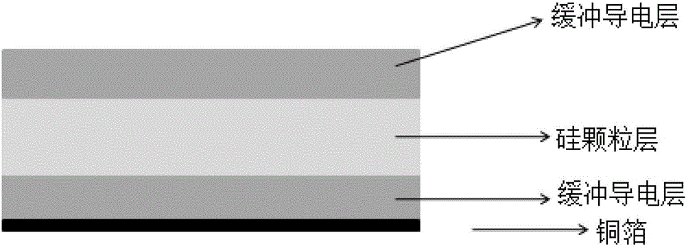
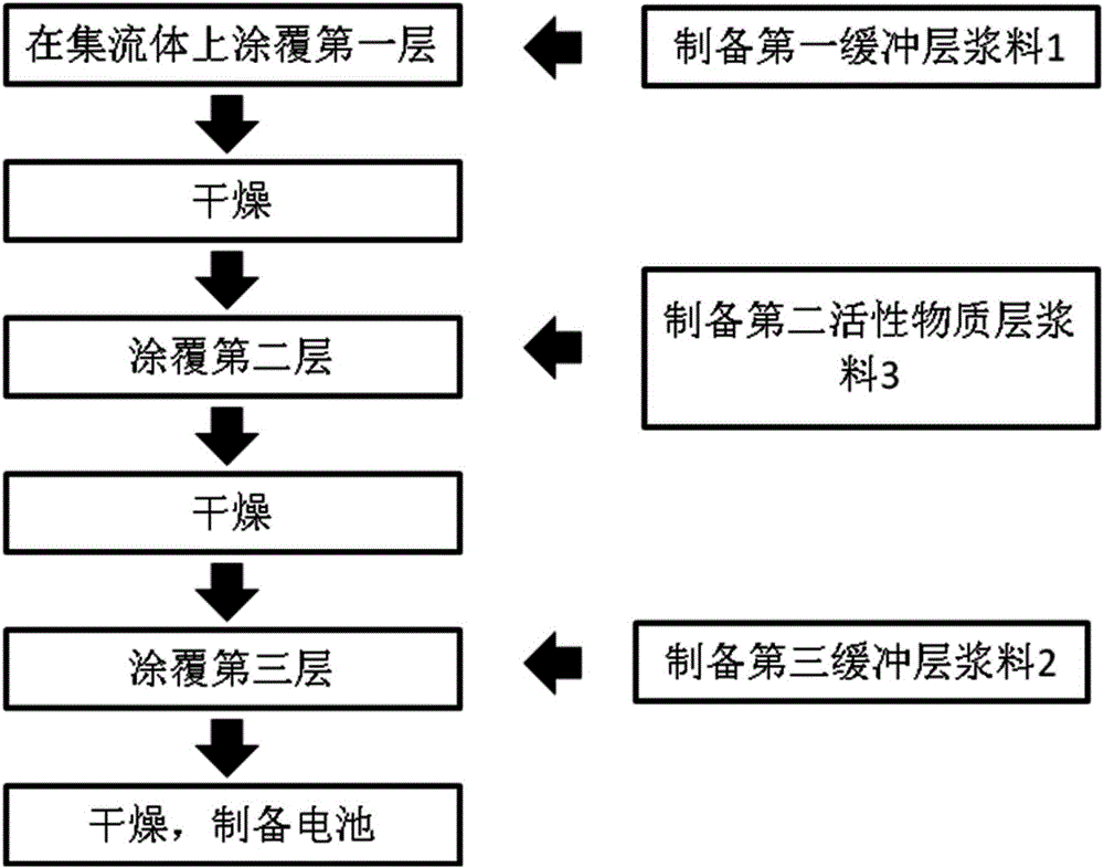
[0070] The process flow chart of the electrode sheet preparation method provided by the embodiment of the present invention is as follows figure 2 shown, including:

[0071] Coating the first conductive layer slurry (first buffer layer slurry) on the surface of the current collector and drying to obtain the first conductive layer;

[0072] Coating the first silicon material layer slurry (second active material layer slurry) on the surface of the first conductive layer and then drying to obtain the first silicon material layer;

[0073] The outer conductive layer slurry (third buffer layer slurry) is coated on the surface of the first silicon material layer and then dried to form an outer conductive layer to obtain an electrode sheet.

[0074] In the present invention, the thickness of the coating is such that the thickness of the obtained first conductive layer is consistent with the thickness of the first conductive layer described in the above technical solution, which wil...

Embodiment 1

[0087] 60g of acetylene black (carbon material) and 40g of polyvinylidene fluoride (PVDF binder) were dissolved in 200g of NMP (N-methylpyrrolidone) solvent to obtain the first conductive layer slurry;

[0088] Prepare the outer conductive layer slurry according to the preparation method of the conductive layer slurry;

[0089] 80g, 325 mesh pure silicon granular material, 10g of acetylene black (conductive agent) and 10g of PVDF (binder) were dissolved in 100g of NMP solvent to obtain the first silicon material layer slurry;

[0090] Coating the conductive layer slurry on the surface of copper foil with a thickness of 15 microns and drying it in a hot air flow drier at 50° C. for 10 minutes to obtain a first conductive layer with a thickness of 100 microns;

[0091] Coating the silicon material layer slurry on the surface of the conductive layer with a doctor blade and drying in a hot air flow drier at 50° C. for 10 minutes to obtain a first silicon material layer with a thic...

Embodiment 2

[0095] The carbon nanotube (carbon material) of 60g and the carboxymethyl cellulose (CMC binding agent) of 40g are dissolved in the secondary water solvent of 200g, obtain the first conductive layer slurry;

[0096] Prepare the outer conductive layer slurry according to the preparation method of the conductive layer slurry;

[0097] 80g, 50nm of pure silicon particle material, 10g of carbon nanotubes (conductive agent) and 10g of CMC (bonding agent) were dissolved in 150g of secondary water solvent to obtain the first silicon material layer slurry;

[0098] Coating the conductive layer slurry on the surface of the copper foil with a thickness of 15 microns and drying at 50° C. for 10 minutes in a hot air flow drier to obtain a first conductive layer with a thickness of 50 microns;

[0099] Coating the silicon material layer slurry on the surface of the conductive layer with a doctor blade and drying in a hot air flow drier at 50° C. for 10 minutes to obtain a first silicon mat...


PUM

PropertyMeasurementUnit
thicknessaaaaaaaaaa
thicknessaaaaaaaaaa
particle sizeaaaaaaaaaa

Abstract

The invention provides an electrode plate which comprises a current collector layer, a first conductive layer, an outer conductive layer and a first silicon material layer, wherein the first conductive layer is arranged on the surface of the current collector layer; the first silicon material layer is arranged on the surface of the outer conductive layer; n groups of silicon material layers and conductive layers are sequentially and alternatively arranged between the first conductive layer and the first silicon material layer. The invention further provides a lithium ion battery which comprises the electrode plate provided by the technical scheme of the invention. According to the electrode plate, the conductive layers have a relatively good buffer function on the silicon material layer, after lithium is embedded, the size of the silicon material layer is increased, then conductive layers on two sides can be compressed, in a lithium removed state, the size of the silicon material layer is reduced and the thickness is recovered, and the conductive layers on two sides are elastic and can be recovered to original thickness, so that due to the multi-layer electrode plate structure, a sufficient buffer space can be provided for the silicon material layer, and along with shrinkage of the silicon material layer, relatively good stability and interface contact property of the multi-layer structure can be maintained, and adverse influence caused by silicon material size change in the battery circulation process can be avoided.

Description

technical field [0001] The invention relates to the technical field of ion batteries, in particular to an electrode sheet and a lithium ion battery. Background technique [0002] In recent years, due to the pressure of environmental pollution and energy scarcity, countries are striving to find environmentally friendly and sustainable energy sources. Green, high-energy and environment-friendly energy storage devices such as lithium-ion batteries and supercapacitors, which appeared in the 1990s, have become the most eye-catching power sources due to their advantages such as high energy density, long cycle life, and high working pressure. [0003] The traditional lithium-ion battery is made of metal oxide and graphite, and its energy density is 150Ah / kg. However, this lithium-ion battery with low energy density cannot meet the current market demand for consumer digital products and power products. Silicon has a capacity ten times higher than the energy density of graphite, and...

Claims


Application Information

Patent Timeline
Patent Type & Authority Applications(China)
IPC IPC(8): H01M4/13H01M4/38H01M10/0525
CPCH01M4/13H01M4/386H01M10/0525Y02E60/10
Inventor 王宏宇李超齐力
Owner CHANGCHUN INST OF APPLIED CHEMISTRY - CHINESE ACAD OF SCI
Why Eureka
Try Eureka