Biomembrane process packing ball

A biofilm method and filler ball technology, applied in the field of filler balls and asymmetric impeller biofilm method filler balls, can solve the problems of difficult biofilm growth, low flow rate, waste of design space, etc., to achieve ideal treatment effects and reduce resistance. , the effect of easy cleaning

Active Publication Date: 2016-07-27
湖南正源金山水务有限公司
View PDF9 Cites 3 Cited by
  • Summary
  • Abstract
  • Description
  • Claims
  • Application Information

AI Technical Summary

Problems solved by technology

[0007] Since biofilm sewage treatment uses a fixed container for centralized sewage treatment, in the container, the influence of the water flow design will flow according to a certain line, and the aeration treatment also makes the water flow have a certain law, so the water flow inside the treatment container It is easy to form a fixed path, which has become a key issue restricting the effect of sewage treatment
In the actual use of the above-mentioned fillers, because after a period of use, the biofilm grows relatively better in areas with low water flow rates, and it is relatively difficult for biofilms to grow in areas with fast and regular flow rates. The lower and lower, the fixed water flow channel is gradually formed inside the treatment equipment, the biofilm cannot play its due role, a lot of design space is wasted, and it is difficult to achieve the ideal effect

Method used


Image

  • Biomembrane process packing ball
  • Biomembrane process packing ball
  • Biomembrane process packing ball

Examples


Embodiment 1

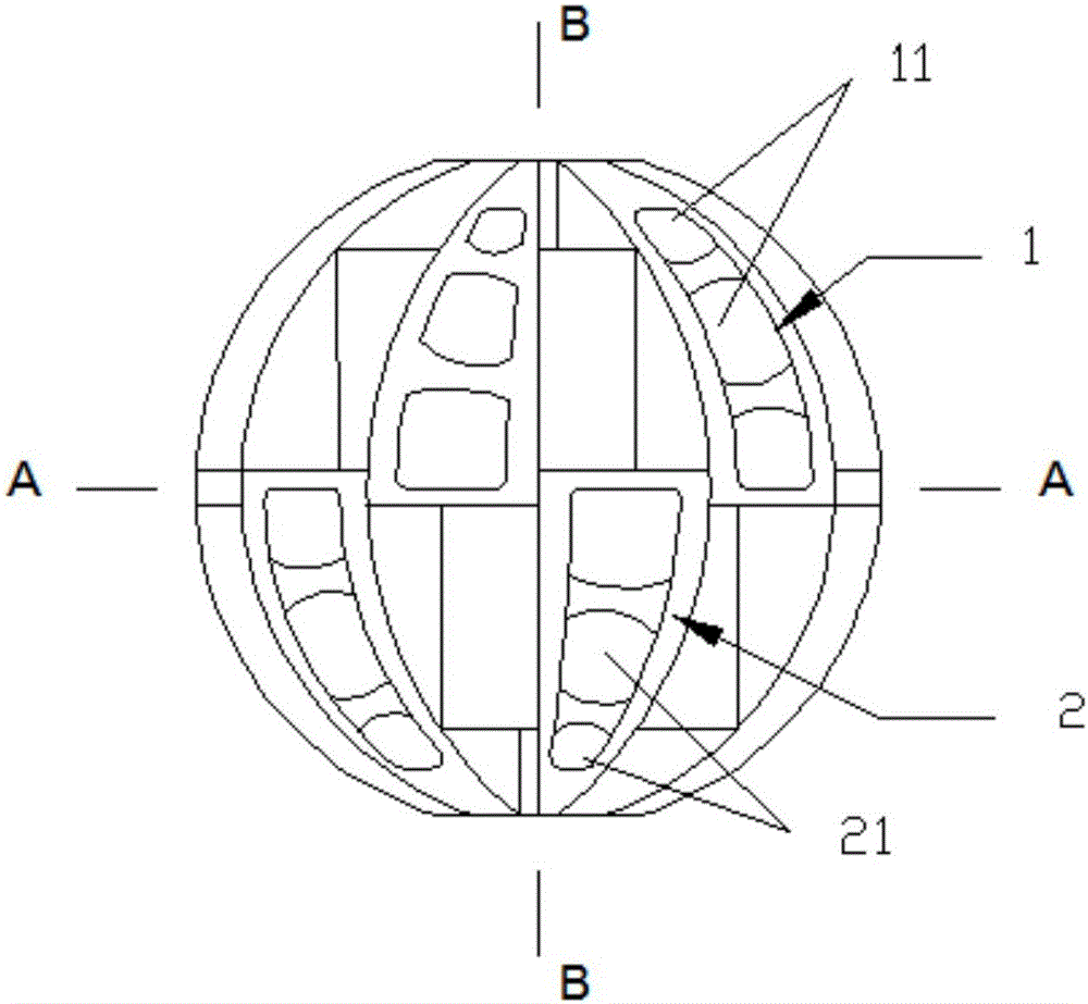
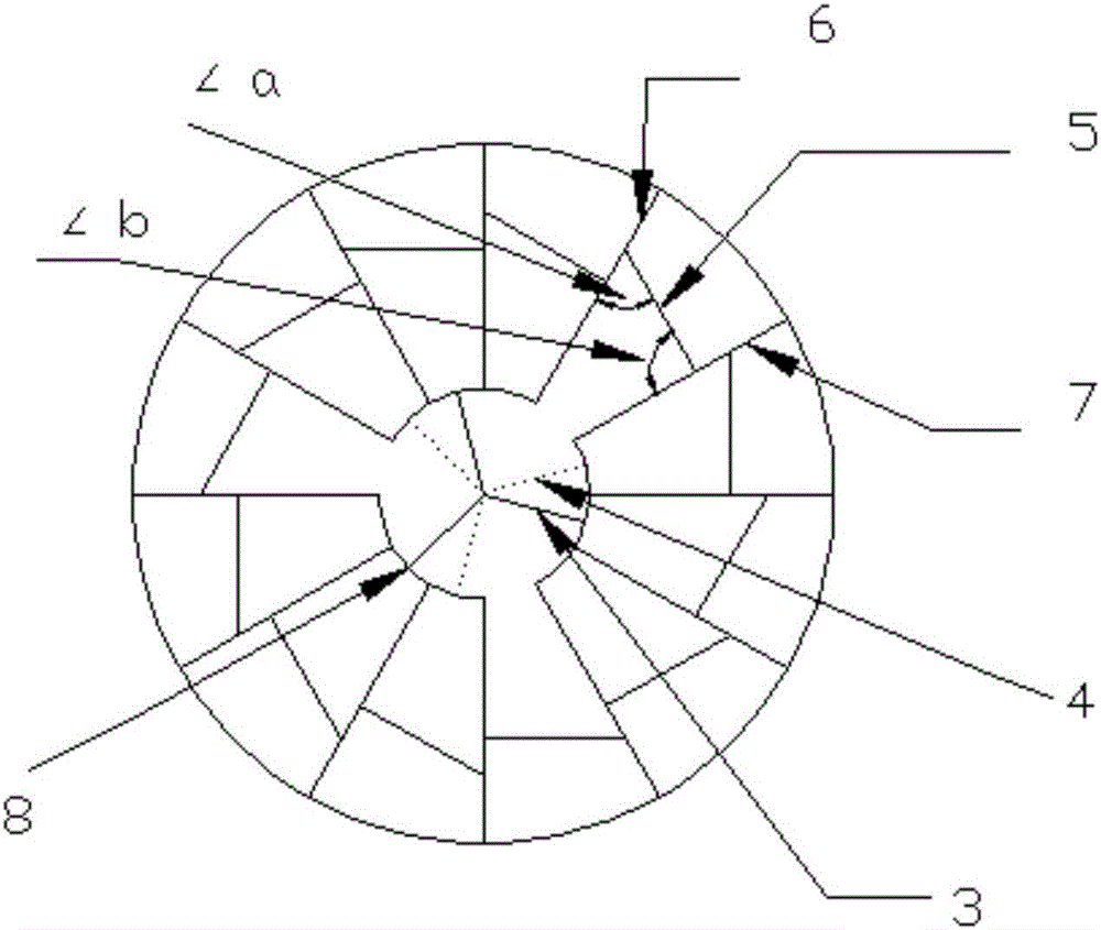
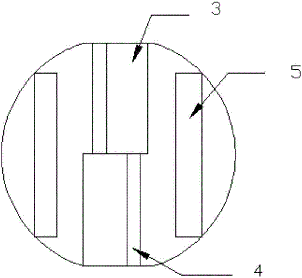
[0060] Such as Figure 1-3 As shown, this embodiment provides a biofilm packing ball, which has a non-symmetrical impeller structure, and any cross-section passing through the center of the ball, the two parts that divide the packing ball are not symmetrical with respect to the cross-section.

[0061] The filler ball is mainly composed of several blades, including spherical blades, axial blades, tangential blades and radial blades. The spherical blades include upper and lower hemispherical spherical blades, and the axial blades include upper and lower hemispherical axial blades;

[0062] Specifically, in this embodiment, the filler balls include:

[0063] The upper hemisphere axial blade 3 and the corresponding lower hemisphere axial blade 4, the upper hemisphere axial blade 3 and the lower hemisphere axial blade 4 are staggered by 30° (such as figure 2 shown); the upper hemisphere axial blade 3 and the lower hemisphere axial blade 4 are trident impeller structures, and the ...

Embodiment 2

[0078] The difference between this embodiment and embodiment 1 is that

[0079] The radial blades of this embodiment are provided with elongated water holes, which can increase the water flow. The structural design of the strip-shaped water holes on the radial blades will reduce the overall specific surface area of ​​the filler ball to a certain extent, so the size of the strip-shaped water holes should be as small as possible while ensuring smooth water flow.

Embodiment 3

[0081] The difference between this embodiment and embodiment 1 is that

[0082] In this embodiment, the height of the axial blades of the upper hemisphere is not equal to the height of the axial blades of the lower hemisphere, and the width is consistent, and the radius of the filler ball is 5cm;

[0083] The height of the axial blade of the upper hemisphere is 0.6 times the radius R of the filler ball, which is 3.0cm;

[0084] The height of the axial blade of the lower hemisphere is 1.2 times the radius R of the filler ball, which is 6.0cm;

[0085] The height of the tangential blade is 1.8 times the radius R, which is 9.0 cm.


PUM

PropertyMeasurementUnit
radiusaaaaaaaaaa

Abstract

A biomembrane process packing ball is of a non-plane symmetry impeller structure and comprises a spherical blade, an axis blade, tangential blades and radial blades.A plurality of water through holes are formed in the spherical blade which comprises upper semispherical blades and lower semispherical blades.The axis blade comprises upper semispherical blades and lower semispherical blades.The upper semispherical blades and the lower semispherical blades surround the upper semispherical axis blades and the lower semispherical axis blades at intervals.The upper semispherical axis blades and the lower semispherical axis blades are staggered by a certain angle.The adjacent upper and lower semispherical blades are in overlapped connection in a staggered mode.The radial blades are arranged at the overlapped connection and connected with the upper and lower semispherical axis blades.The upper and lower semispherical axis blades are of a three-fork type impeller structure.One fork corresponds to an arc connecting piece.The corresponding spherical blades and the radial blades are connected with the axis blades through the arc connecting pieces.The tangential blades are arranged between the two adjacent radial blades and form different included angles with the adjacent radial blades.The biomembrane process packing ball is large in specific area, more turbulent flows can be generated to achieve the better sewage treatment effect, cleaning is convenient, and the cost is low.

Description

technical field [0001] The invention relates to a filler ball, in particular to an asymmetric impeller type biofilm method filler ball, which belongs to the technical field of biofilm filler. Background technique [0002] Common sewage treatment methods include activated sludge method, biofilm method, anaerobic biological treatment method, chemical precipitation method, redox method, ion exchange method, membrane separation method, etc.; among them: activated sludge method and biofilm method belong to biological Chemical conversion technology; chemical precipitation method and redox method belong to chemical conversion technology; ion exchange method and membrane separation method belong to physical and chemical separation technology. The biofilm method is a wastewater treatment method that makes wastewater contact with a biofilm grown on the surface of a fixed support, and utilizes biodegradation or conversion of organic pollutants in wastewater. As an ancient and new sewa...

Claims


Application Information

Patent Timeline
Patent Type & Authority Applications(China)
IPC IPC(8): C02F3/10
CPCC02F3/109Y02W10/10
Inventor 易榴意向娟雷良杨春平
Owner 湖南正源金山水务有限公司
Why Eureka
Try Eureka