2D carbon/silicon-silicon carbide composite material pin preparation method and preparation method and structure of 2D carbon/silicon-silicon carbide composite material pin preform

A technology of composite materials and silicon carbide, which is applied in the field of corrosion-resistant and oxidation-resistant composite materials, high temperature resistance, preparation and processing of ceramic matrix composite materials, and high strength. It can solve unstable product performance, long production cycle, and high cost. problems, to achieve the effect of uniform force, improved mechanical properties, and high connection strength

Active Publication Date: 2016-08-10
XIAN XINGUI CERAMIC COMPOSITE MATERIAL CO LTD
6 Cites 17 Cited by

AI-Extracted Technical Summary

Problems solved by technology

[0005] In order to overcome the shortcomings of the preparation technology of pin-punched C/SiC composite material (CVI process) pins with complex structures, such as long production cycle, high cost, and large differences in product...

Method used

The present invention adopts two-dimensional carbon cloth tiling and oblique paving to prepare a two-dimensional flat plate prefabricated body with the method of carbon fiber vertical puncture again, first penetrates the pyrolytic carbon protective layer inside the prefabricated body, then adopts CVI (chemical vapor i...

Abstract

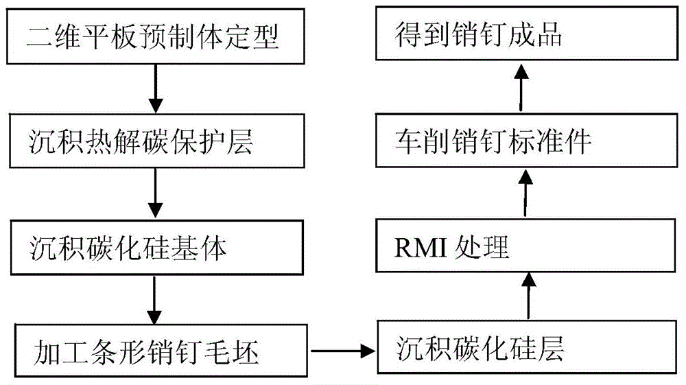
The invention relates to a 2D carbon/silicon-silicon carbide composite material pin preparation method and a preparation method and structure of a 2D carbon/silicon-silicon carbide composite material pin preform. The pin preparation method comprises 1, preparing a preform through horizontal paving (0 degree)-inclined paving (45 degrees) alternative laying of a 2D carbon fabric, graphite mold-based setting and carbon fiber vertical seaming on the multilayer carbon fabric, 2, depositing a pyrolytic carbon protective layer in the preform, 3, carrying out chemical vapor infiltration (CVI) to obtain a silicon carbide base, 4, cutting a flat blank to obtain a strip-shaped pin blank with the square section, 5, carrying out CVI silicon carbide protection of exposed fibers, 6, carrying out reactive melt infiltration (RMI) treatment, 7, milling the pin blank to obtain a pin with a standard size and 8, carrying out examination to obtain a carbon/silicon-silicon carbide composite material pin finished product. Through combination of CVI and RMI, the preparation method has the advantages of low production cost, short production period, low product porosity, high density and batch production. The ceramic-based composite material prepared by the CVI and RMI has shear strength of 80-100MPa at the room temperature.

Application Domain

Technology Topic

Batch productionCeramic matrix composite +11

Image

  • 2D carbon/silicon-silicon carbide composite material pin preparation method and preparation method and structure of 2D carbon/silicon-silicon carbide composite material pin preform
  • 2D carbon/silicon-silicon carbide composite material pin preparation method and preparation method and structure of 2D carbon/silicon-silicon carbide composite material pin preform
  • 2D carbon/silicon-silicon carbide composite material pin preparation method and preparation method and structure of 2D carbon/silicon-silicon carbide composite material pin preform

Examples

  • Experimental program(4)

Example Embodiment

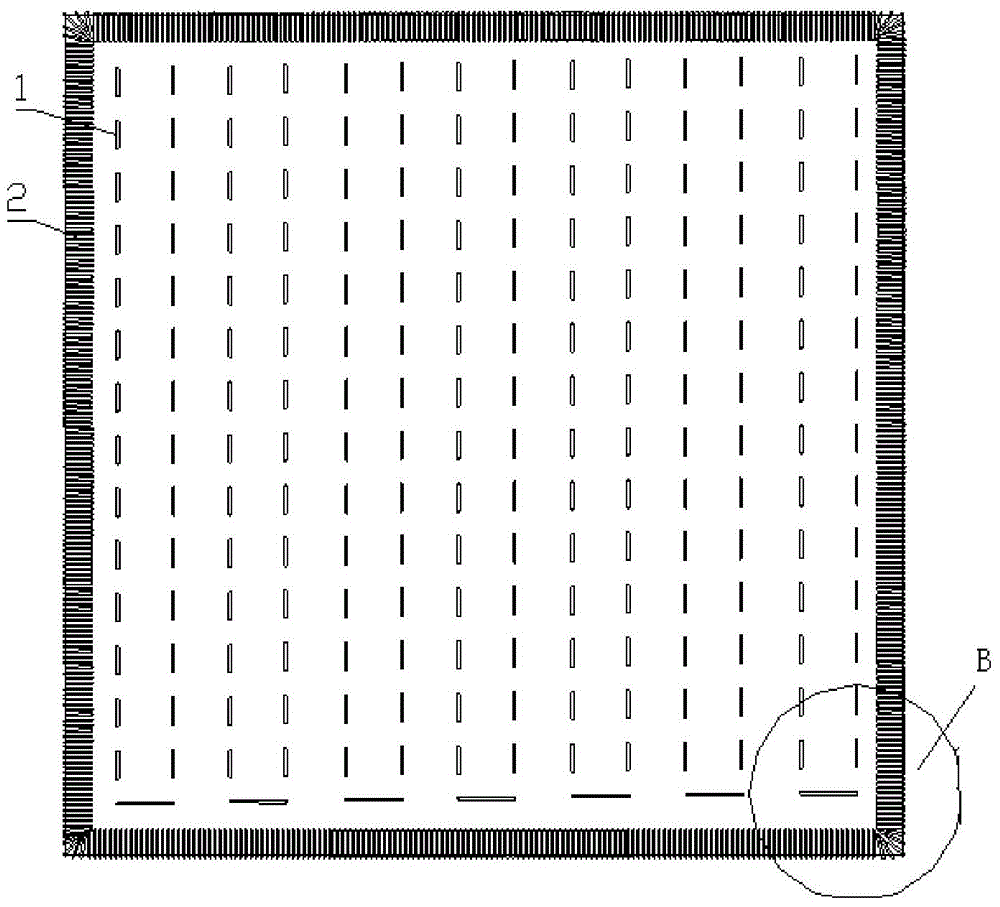
[0051] Such as Figure 2-3 As shown, the two-dimensional carbon/silicon-silicon carbide composite material pin preform of the present invention includes a multilayer two-dimensional carbon cloth, and the included angle of the corresponding fibers of two adjacent layers of the two-dimensional carbon cloth in the multilayer two-dimensional carbon cloth is 45°, the two-dimensional carbon/silicon-silicon carbide composite pin preform also includes a sewing structure. The sewing structure includes a plurality of U-shaped fibers distributed in a square matrix. Single-side vertical penetration of multilayer two-dimensional carbon cloth. The four sides of the multi-layer two-dimensional carbon cloth are stitched with carbon fibers. Sometimes, the ends of two adjacent rows of U-shaped fibers in the square matrix are also provided with a U-shaped fiber. The preparation method of the two-dimensional carbon/silicon-silicon carbide composite material pin preform includes the following steps:
[0052] 1) Place the graphite plate with holes horizontally;
[0053] 2) Spread multiple layers of two-dimensional carbon cloth on the graphite plate until the laminated thickness of the two-dimensional carbon cloth meets the pin diameter and has a processing allowance; the angle between the corresponding fibers of the two adjacent layers of two-dimensional carbon cloth is 45 °;
[0054] 3) Tighten the multilayer two-dimensional carbon cloth and the graphite plate, and erect the graphite plate;
[0055] 4) Fix the graphite plate with the bracket;
[0056] 5) Use fibers to sew carbon cloth vertically through holes set on the graphite plate to make a two-dimensional flat plate preform. After depositing the silicon carbide layer on the two-dimensional flat plate preform, the graphite plate is removed to form a pin preform.

Example Embodiment

[0058] Example 1:
[0059] This embodiment is a method for preparing a two-dimensional carbon/silicon-silicon carbide composite material pin. The specific process is:
[0060] Step 1. Make a two-dimensional flat plate preform. Use two-dimensional carbon cloth to spread alternately in the direction of flat (0°) and oblique (45°) layer by layer (the thickness should be greater than the pin diameter and the machining allowance is left), and the surface should be perforated (8~15× 8~15mm (arrangement method) graphite flat plate flattened the carbon cloth, the arch frame is fixed on the bracket, the carbon fiber is used to pass through each hole, and the carbon cloth is sewn vertically to make a two-dimensional flat preform.
[0061] Step 2, depositing a pyrolytic carbon interface layer. The pyrolytic carbon protective layer is infiltrated into the two-dimensional flat preform through the deposition furnace. The process conditions are: the deposition temperature is 700 ℃, the deposition furnace is evacuated to 5kPa, and the flow rate of propylene gas is 3L/min as the deposition gas, 6L/min Min Ar gas is used as a protective gas, and the deposition time is about 70 hours; a two-dimensional flat plate preform deposited with a protective layer of pyrolytic carbon is obtained.
[0062] Step 3, release and deposit the silicon carbide substrate. Infiltrate the silicon carbide matrix inside the two-dimensional flat plate with the pyrolytic carbon protective layer. The process conditions are: the deposition temperature is 1000 ℃, the deposition furnace is evacuated to 5 kPa, and Ar gas with a flow rate of 6L/min is used as the protective gas, and the flow rate is 6L/min of H 2 As the carrier gas, trichloromethylsilane is loaded into the deposition furnace to react inside the two-dimensional plate to form a silicon carbide matrix, which is deposited on the pyrolytic carbon protective layer inside the two-dimensional plate to generate density (or pores). Rate) about 1.3~1.5g/cm 3 Composite material flat plate; the temperature of the trichloromethylsilane is 30℃~35℃, H 2 The molar mass ratio to trichloromethylsilane is 9-11, and the deposition time is about 70h.
[0063] Step 4, processing the strip pin blank; first use a grinder to grind the upper and lower surfaces of the two-dimensional flat plate to ensure that the thickness is greater than the pin diameter (leave a machining allowance). Clean the surface of the plate, as long as there is no particles, and then cut the plate into a long strip of square section.
[0064] Step 5, deposit the silicon carbide layer; put the strip blank into the furnace to deposit the silicon carbide layer, the deposition temperature is 1000 ℃, the deposition furnace is evacuated to 5kPa, and Ar gas with a flow rate of 6L/min is used as the protective gas, and the flow rate is 6L /min of H 2 The gas is used as the carrier gas, and the trichloromethylsilane is loaded into the deposition furnace to react on the inside and surface of the pin blank, and the resulting density (or porosity) is about 1.5~1.7g/cm 3 Composite material blanks. The temperature of the trichloromethylsilane is 30℃~35℃, H 2 The molar mass ratio to trichloromethylsilane is 9-11, and the deposition time is about 70h.
[0065] Step 6, RMI treatment; discharge the strip pin blanks coated with boron nitride slurry into the crucible side by side, and embed the strip pin blanks with silicon powder and silicon carbide powder (mixed in a mass ratio of 1:1 to 2) , Put into the melt infiltration furnace for high temperature treatment, the treatment temperature is 1300℃, the furnace is evacuated to 3kPa, and Ar gas with a flow rate of 2L/min is used as the protective gas, the penetration time is about 70h, and the density (or porosity) is generated About 1.9~2.1g/cm 3 Strip blank after siliconizing.
[0066] Step 7, processing standard pin parts; clamp the strip-shaped pin blanks impregnated with melt on the lathe, and cut into standard pin parts. Then the standard pin parts are ultrasonically cleaned and dried to obtain a finished product of two-dimensional carbon/silicon-silicon carbide composite material pins.

Example Embodiment

[0067] Example 2:
[0068] Step 1. Make a two-dimensional flat plate preform. Use two-dimensional carbon cloth to spread alternately in the direction of flat (0°) and oblique (45°) layer by layer (the thickness should be greater than the pin diameter and the machining allowance is left), and the surface should be perforated (8~15× 8~15mm (arrangement method) graphite flat plate flattened the carbon cloth, the arch frame is fixed on the bracket, the carbon fiber is used to pass through each hole, and the carbon cloth is sewn vertically to make a two-dimensional flat preform.
[0069] Step 2, depositing a pyrolytic carbon interface layer. The pyrolytic carbon protective layer is infiltrated into the two-dimensional flat plate preform through the deposition furnace. The process conditions are: the deposition temperature is 800 ℃, the deposition furnace is evacuated to 3 kPa, and the propylene gas with a flow rate of 4L/min is used as the deposition gas, 8L/min. Min Ar gas is used as a protective gas, and the deposition time is about 70 hours; a two-dimensional flat plate preform deposited with a protective layer of pyrolytic carbon is obtained.
[0070] Step 3, release and deposit the silicon carbide substrate. Infiltrate the silicon carbide matrix inside the two-dimensional flat plate with the pyrolytic carbon protective layer. The process conditions are: the deposition temperature is 1050℃, the deposition furnace is evacuated to 3kPa, and the Ar gas with a flow rate of 8L/min is used as the protective gas, and the flow rate is 8L/min of H 2 As the carrier gas, trichloromethylsilane is loaded into the deposition furnace to react inside the two-dimensional plate to form a silicon carbide matrix, which is deposited on the pyrolytic carbon protective layer inside the two-dimensional plate to generate density (or pores). Rate) about 1.3~1.5g/cm 3 Composite material flat plate; the temperature of the trichloromethylsilane is 30℃~35℃, H 2 The molar mass ratio to trichloromethylsilane is 9-11, and the deposition time is about 70h.
[0071] Step 4, processing the strip pin blank; first use a grinder to grind the upper and lower surfaces of the two-dimensional flat plate to ensure that the thickness is greater than the pin diameter (leave a machining allowance). Clean the surface of the plate, as long as there is no particles, and then cut the plate into a long strip of square section.
[0072] Step 5, deposit a silicon carbide layer; put the strip blank into the furnace to deposit the silicon carbide layer, the deposition temperature is 1050°C, the deposition furnace is evacuated to 3kPa, and Ar gas with a flow rate of 8L/min is used as a protective gas, and the flow rate is 8L /min of H 2 The gas is used as the carrier gas, and the trichloromethylsilane is loaded into the deposition furnace to react on the inside and surface of the pin blank, and the resulting density (or porosity) is about 1.5~1.7g/cm 3 Composite material blanks. The temperature of the trichloromethylsilane is 30℃~35℃, H 2 The molar mass ratio to trichloromethylsilane is 9-11, and the deposition time is about 70h.
[0073] Step 6, RMI treatment; discharge the strip pin blanks coated with boron nitride slurry into the crucible side by side, and embed the strip pin blanks with silicon powder and silicon carbide powder (mixed in a mass ratio of 1:1 to 2) , Put it into the melt infiltration furnace for high temperature treatment, the treatment temperature is 1350℃, the furnace is evacuated to 2kPa, and Ar gas with a flow rate of 3L/min is used as the protective gas, the penetration time is about 70h, and the density (or porosity) is generated About 1.9~2.1g/cm 3 Strip blank after siliconizing.
[0074] Step 7, processing standard pin parts; clamp the strip-shaped pin blanks impregnated with melt on the lathe, and cut into standard pin parts. Then the standard pin parts are ultrasonically cleaned and dried to obtain a finished product of two-dimensional carbon/silicon-silicon carbide composite material pins.

PUM

PropertyMeasurementUnit
Angle45.0deg
Shear strength80.0 ~ 100.0mPa
Shear strength81.0 ~ 105.0mPa
tensileMPa
Particle sizePa
strength10

Description & Claims & Application Information

We can also present the details of the Description, Claims and Application information to help users get a comprehensive understanding of the technical details of the patent, such as background art, summary of invention, brief description of drawings, description of embodiments, and other original content. On the other hand, users can also determine the specific scope of protection of the technology through the list of claims; as well as understand the changes in the life cycle of the technology with the presentation of the patent timeline. Login to view more.

Similar technology patents

Classification and recommendation of technical efficacy words

  • Improve mechanical properties
  • Even by force

Driving structure and optical anti-shake camera

Owner:DONGGUAN PRECISION PHOTONICS LTD
Why Eureka
Try Eureka