
Direct combustion type waste gas treatment and heat energy utilization system and utilization method

A waste gas treatment, direct combustion technology, applied in the combustion method, combustion type, heating device and other directions, can solve the problems of harm to human health, secondary pollution, high energy consumption, etc., to achieve the effect of convenient incineration and reasonable utilization of energy

Active Publication Date: 2016-08-17
张家港市弘扬机械设备有限公司
View PDF5 Cites 4 Cited by
  • Summary
  • Abstract
  • Description
  • Claims
  • Application Information

AI Technical Summary

Problems solved by technology

[0002] While the rapid development of industry has brought wealth, it has also caused pollution to the environment. Organic waste gas is a common pollutant emitted by industry. The coating production line contains xylene, ethylene glycol and other organic compounds. If these waste gases are not treated Disposal, direct discharge into the atmosphere will cause serious pollution to the environment and endanger human health
Traditional organic waste gas purification methods include adsorption method, condensation method and direct combustion method, etc. These methods are prone to secondary pollution, high energy consumption, and are easily limited by the concentration and temperature of organic waste gas.

Method used


Image

  • Direct combustion type waste gas treatment and heat energy utilization system and utilization method
  • Direct combustion type waste gas treatment and heat energy utilization system and utilization method

Examples


Embodiment 1

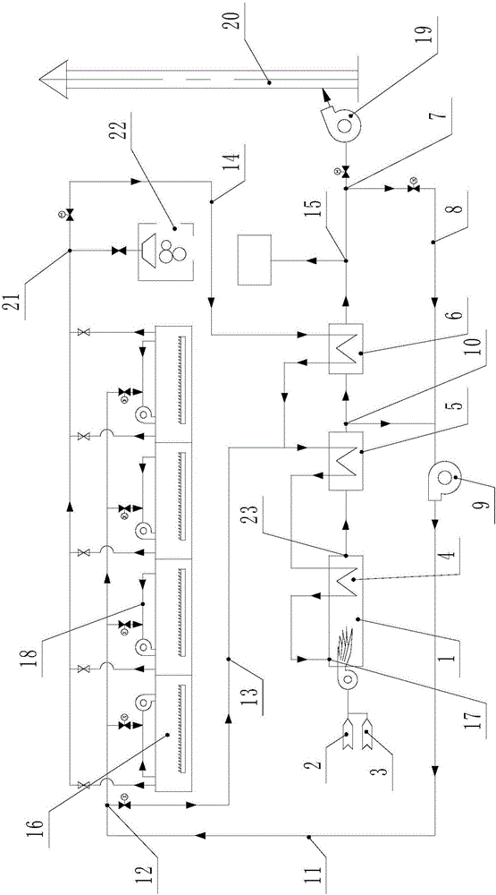
[0023] like figure 1 As shown, a direct-fired waste gas treatment and heat energy utilization system includes an oven 16, which is provided with a circulating air duct 18 with both ends communicating with the interior of the oven 16, and a circulating fan is arranged on the circulating air duct 18. This circulating air duct 18 is communicated with the hot blast supply system, and the hot blast supply system includes an incinerator 1, and the incinerator 1 is provided with an incinerator, and the incinerator is connected with the fuel supply pipe 2 and the combustion air supply pipe 3, and the incinerator 1 is provided with an exhaust port 23 and a waste gas recovery port 17. The waste gas recovery port 17 corresponds to the combustion position of the incinerator 1. The recovered organic waste gas is directly burned and decomposed into carbon dioxide and water at the combustion position. The waste gas recovery port 17 It communicates with the oven 16 through the waste gas recov...

Embodiment 2

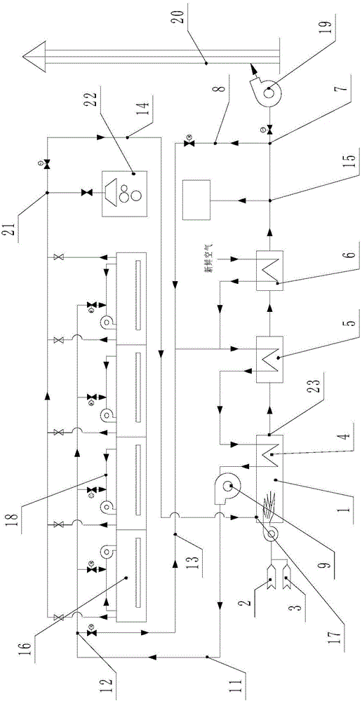
[0033] like figure 2 As shown, the basic idea of ​​this embodiment is the same as that of the embodiment, both are to collect the organic waste gas produced by the oven and send it to the incinerator 1 for incineration, but the hot air generated after incineration in the incinerator 1 is not directly supplied To the oven 16, the reason is mainly to prevent the incomplete combustion of the organic waste gas in the incinerator 1, thereby causing the hot air generated by the combustion to bring new pollution to the oven 16 when the hot air is sent to the oven 16. At this time, the air supply pipeline 11 Directly communicate with the fresh air source, then the air supply line 11 exchanges heat with the hot air burned by the incinerator 1, and the fresh air is heated to a certain stability and then supplied to the oven 16 for heating. At this time, the air supply pipeline 11 is not communicated with the exhaust pipeline, but is communicated with the fresh air source, and the air s...


PUM


Abstract

The invention discloses a direct combustion type waste gas treatment and heat energy utilization system. The direct combustion type waste gas treatment and heat energy utilization system comprises an oven. The upper portion of the oven communicates with a hot air supply system. The hot air supply system comprises an incinerator. An exhaust port and a waste gas recovery port are formed in the incinerator. The waste gas recovery port communicates with the oven through a waste gas recovery pipeline. The exhaust port is connected with an exhaust pipeline. A circulating air pipe of the oven is connected with an air supply pipeline. An air supply fan is arranged on the air supply pipeline. One end of the air supply pipeline communicates with the circulating air pipe. The other end of the air supply pipeline communicates with the exhaust pipeline, or the other end of the air supply pipeline communicates with a fresh air source, and the air supply pipeline and the exhaust pipeline are connected through a heat exchanger. According to the direct combustion type waste gas treatment and heat energy utilization system, organic waste gas can be delivered into the incinerator to be burnt, and generated heat energy is supplied to the oven, so that the organic waste gas is treated, the heat energy is recovered and reutilized, and emission of polluting gas is reduced. The invention further discloses a waste gas treatment and heat energy utilization method. By the adoption of the method, the treatment rate of the organic waste gas is increased, and energy is saved.

Description

technical field [0001] The invention relates to a direct combustion waste gas treatment and heat energy utilization system, and also relates to a waste gas treatment and heat energy utilization method matched with the waste gas treatment and heat energy utilization system. Background technique [0002] While the rapid development of industry has brought wealth, it has also caused pollution to the environment. Organic waste gas is a common pollutant emitted by industry. The coating production line contains xylene, ethylene glycol and other organic compounds. If these waste gases are not treated Disposal and direct discharge into the atmosphere will cause serious pollution to the environment and endanger human health. Traditional organic waste gas purification methods include adsorption method, condensation method, and direct combustion method. These methods are prone to secondary pollution, high energy consumption, and are easily limited by the concentration and temperature o...

Claims


Application Information

Patent Timeline
Patent Type & Authority Applications(China)
IPC IPC(8): F23G7/06F26B21/00F26B23/02
CPCF23G7/065F23G2202/106F23G2204/103F23G2206/00F26B21/001F26B23/022Y02P70/10
Inventor 朱鹏朱良才
Owner 张家港市弘扬机械设备有限公司
Features
  • Generate Ideas
  • Intellectual Property
  • Life Sciences
  • Materials
  • Tech Scout
  • Unparalleled Data Quality
  • Higher Quality Content
  • 60% Fewer Hallucinations
Learn More