Wire feeding mechanism, wire feeding device and additive manufacturing equipment based on additive manufacturing technology

A technology of wire feeding mechanism and wire feeding device, which is applied in the field of additive manufacturing, can solve problems such as prolonging working hours, contamination of workpieces, increasing the number of vacuum system degassing and pumping, and achieves the effect of improving processing efficiency and quality

Active Publication Date: 2016-10-12
XIAN ZHIRONG METAL PRINTING SYST CO LTD
View PDF5 Cites 16 Cited by
  • Summary
  • Abstract
  • Description
  • Claims
  • Application Information

AI Technical Summary

Problems solved by technology

[0003] In the prior art, the wire feeding system provides raw material supply for the electron beam fuse rapid prototyping equipment. At present, the wire feeding mechanism used in the electron beam fuse device is set in a vacuum chamber, that is, the wire feeding mechanism and the fuse deposition part are the same. In the vacuum chamber, the electron beam fuse forming equipment is characterized by a fast deposition rate of the fuse, and the deposition rate is as high as 15kg / h. Taking the ordinary 20kg wire as an example, the melting time is only a few hours, so the wire needs to be changed frequently. During the filament process, the vacuum system must be closed and the vacuum chamber door must be opened, thus increasing the number of deflation and pumping of the vacuum system. At the same time, in order to prevent high-temperature oxidation of the printed parts, it is necessary to cool the metal printed parts to room temperature in a vacuum environment, so that The working time is extended. In addition, frequent opening of the vacuum chamber door may cause problems such as contamination of the processed parts, especially the repeated heating and cooling during the working process, which increases the internal stress of the printed parts.
If the wire feeding mechanism is placed outside the vacuum chamber, since the wire feeding pipeline is connected to the atmospheric environment, the wire feeding process will inevitably bring gas into the vacuum chamber through the wire feeding pipeline, resulting in insufficient vacuum in the vacuum chamber and affecting the beam spot of the electron beam. Quality and print quality

Method used


Image

  • Wire feeding mechanism, wire feeding device and additive manufacturing equipment based on additive manufacturing technology
  • Wire feeding mechanism, wire feeding device and additive manufacturing equipment based on additive manufacturing technology
  • Wire feeding mechanism, wire feeding device and additive manufacturing equipment based on additive manufacturing technology

Examples


Embodiment 1

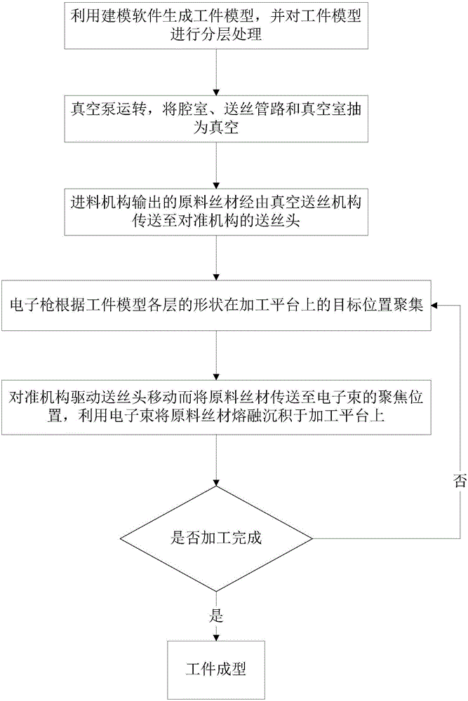
[0051] Embodiment 1: Use CAD to model the three-dimensional model of the pre-processed part, use data processing software to process the model layer by layer and convert it into a numerical control program, and then import it into the equipment control system. The fuse deposition process is expressed as follows:

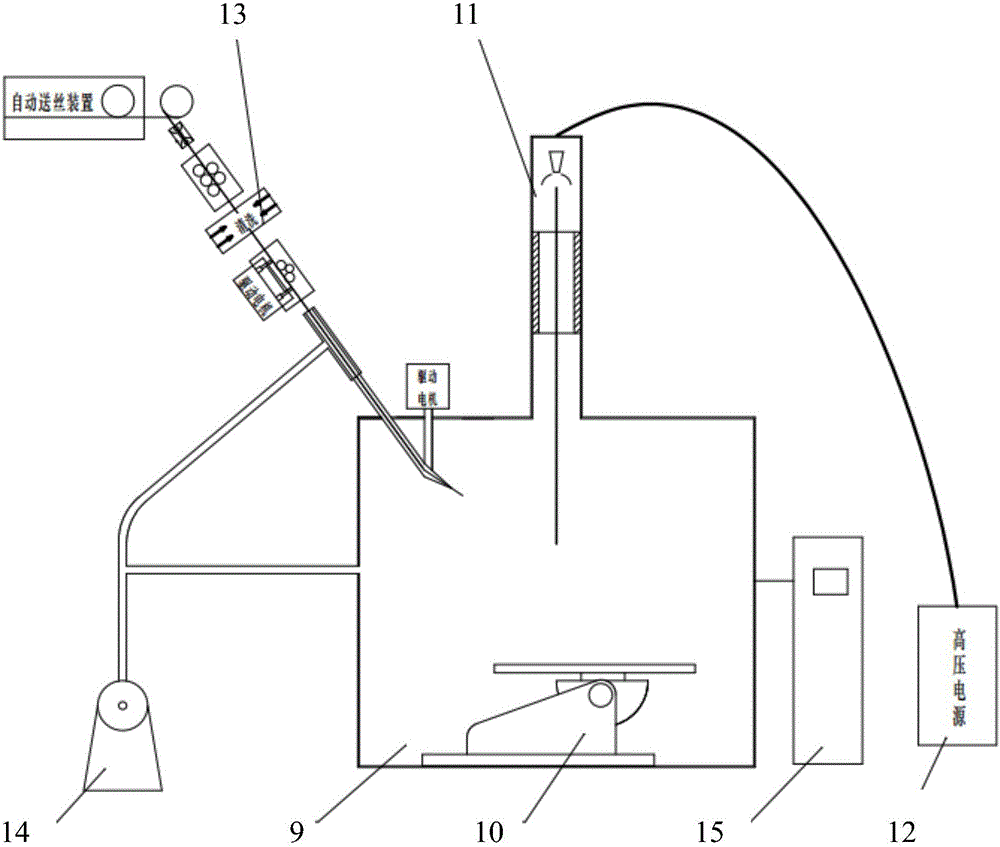
[0052] Step a, the wire storage tray filled with wire material is pushed to the wire feeding station;

[0053] Step b. Place a metal substrate with the same or similar composition as the printed workpiece on the working platform in the vacuum chamber, as the base layer for the first layer of metal melting;

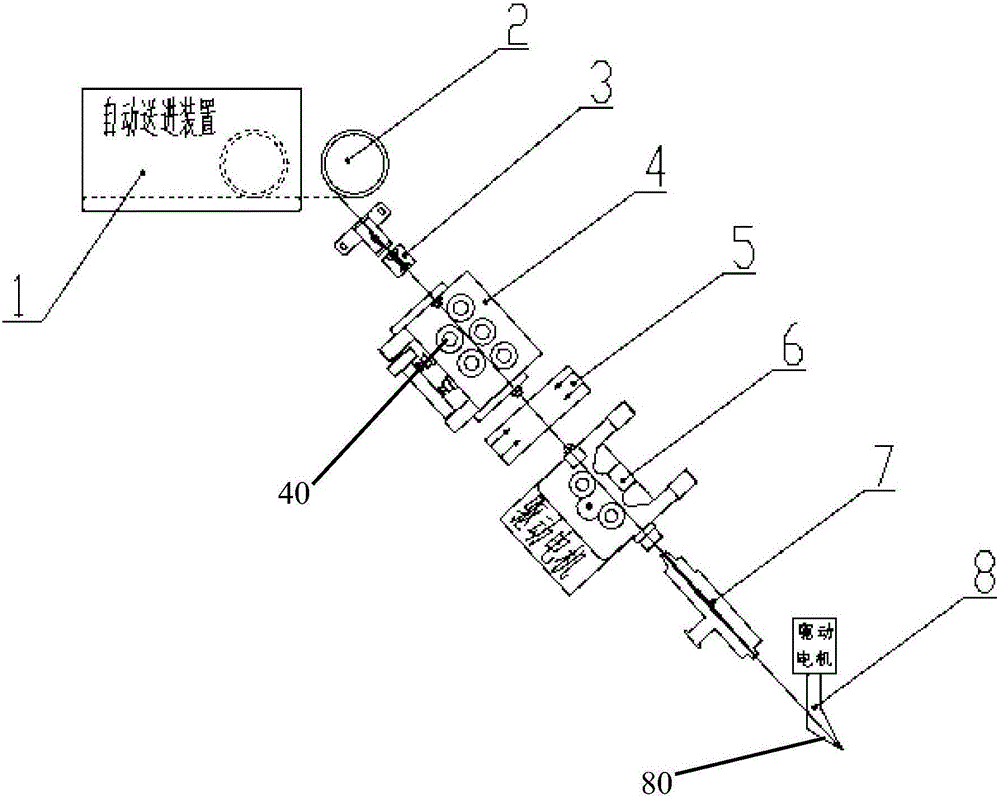
[0054] Step c. Pass the metal wire on the wire storage tray through the wire straightening mechanism, after cleaning and drying, enter the wire feeding mechanism, and then use the wire feeding motor to drive it through the metal inner tube with small holes and the wire feeding soft tube until the wire feeder comes out of the wire.

[0055] Step d, the motor of ...


PUM


Abstract

The invention discloses additive manufacturing equipment. The additive manufacturing equipment comprises a vacuum chamber, an electronic gun, a wire feeding device, a vacuum pump and a master control system; a machining platform is arranged at the bottom of the vacuum chamber; the electronic gun is connected to a high voltage power supply, and an electronic beam output end of the electronic gun faces the machining platform; the wire feeding device is arranged outside the vacuum chamber and comprises a vacuum wire feeding mechanism, the vacuum wire feeding mechanism comprises a shell, a closed cavity is formed inside the shell, a wire feeding pipeline used for conveying raw wires is arranged inside the cavity, the two ends of the wire feeding pipeline penetrate through the shell, the shell is provided with an air nozzle used for vacuumizing the cavity, a plurality of air holes are formed in the wire feeding pipeline, and air inside the wire feeding pipeline is extracted through the air holes; the vacuum pump communicates with the vacuum chamber and the air nozzle through pipelines; the master control system is used for controlling the working states of the electronic gun, the vacuum pump and the wire feeding device. According to the additive manufacturing equipment, the processing efficiency and the processing quality can be effectively improved.

Description

technical field [0001] The invention relates to the technical field of additive manufacturing, in particular to a wire feeding mechanism, a wire feeding device and additive manufacturing equipment based on additive manufacturing technology. Background technique [0002] There are currently two methods of electron beam additive manufacturing: electron beam melting powder technology and electron beam fuse forming technology. The electron beam melting powder technology uses metal powder as the raw material, which has the disadvantages of difficulty in manufacturing the required metal powder, high cost of use, and low molding efficiency. Electron beam fuse forming can ensure the quality of printed parts to reach the forging level while realizing efficient deposition forming. This technology has the characteristics of no reflection, fast forming speed, high material utilization rate, and high energy conversion efficiency. [0003] In the prior art, the wire feeding system provid...

Claims


Application Information

Patent Timeline
Patent Type & Authority Applications(China)
IPC IPC(8): B22F3/115B33Y30/00
CPCB22F3/115B33Y30/00
Inventor 郭光耀
Owner XIAN ZHIRONG METAL PRINTING SYST CO LTD
Why Eureka
Try Eureka