A double-effect cross flow MVR evaporation and concentration system

An evaporation concentration system and high-efficiency evaporation technology, which is applied in the field of double-effect cross-flow MVR evaporation and concentration systems, can solve the problems of low environmental and economic benefits, limited application scope, and large energy consumption.

Active Publication Date: 2016-11-02
JIANGMEN BAICHUAN ENVIRO TECH CO LTD
View PDF4 Cites 15 Cited by
  • Summary
  • Abstract
  • Description
  • Claims
  • Application Information

AI Technical Summary

Problems solved by technology

The aforementioned three-effect evaporation and concentration method has the problems of high energy consumption, low environmental and economic benefits, and the single-effect MVR evaporation has the problem of l

Method used


Image

  • A double-effect cross flow MVR evaporation and concentration system
  • A double-effect cross flow MVR evaporation and concentration system
  • A double-effect cross flow MVR evaporation and concentration system

Examples


Embodiment approach 1

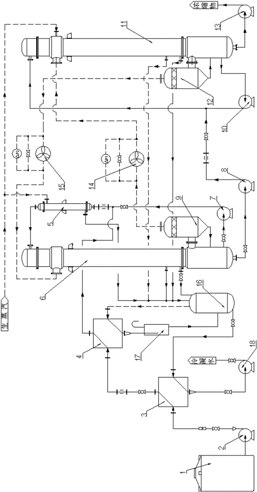
[0031] Implementation Mode 1: As attached figure 1 As shown, the feed-liquid process subsystem of the double-effect cross-flow MVR evaporation and concentration system includes raw material tank 1, feed pump 2, liquid-liquid heat exchanger 3, vapor-liquid heat exchanger 4, one-effect preheater 5, One-effect evaporator 6, one-effect circulation pump 7, one-effect discharge pump 8, one-effect two-phase separator 9, two-effect circulation pump 10, second-effect evaporator 11, second-effect two-phase separator 12, two-effect outlet The material pump 13, the raw material tank 1, the feed pump 2, the cold side of the liquid-liquid heat exchanger 3, and the cold side of the vapor-liquid heat exchanger 4 are sequentially connected in series, and the outlet of the first-effect circulation pump 7 is connected to the first-effect preheater 5 The feed liquid inlet is connected, and the cold side outlet of the vapor-liquid heat exchanger 4 is connected to the pipeline between the outlet of...

Embodiment approach 2

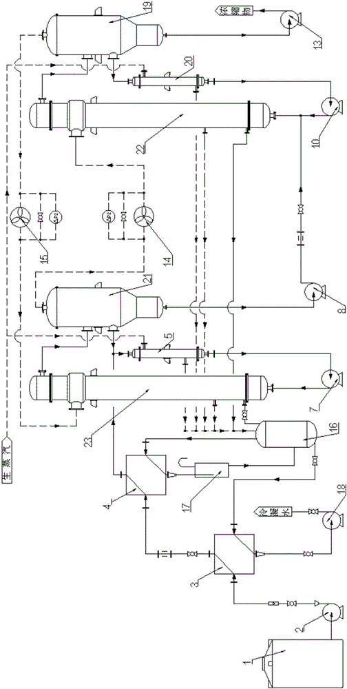
[0034] Implementation mode two: as attached figure 2 As shown, on the basis of Embodiment 1, the second-effect two-phase separator 12 of the feed-liquid process subsystem is replaced by a second-effect three-phase separator 19, and the second-effect evaporator 11 is replaced by a second-effect forced circulation heating body 22; The inlet of the effect circulation pump 10 is connected with the feed liquid outlet of the second effect preheater 20, the outlet of the second effect circulation pump 10 is connected with the feed liquid inlet of the second effect forced circulation heating body 22, and the outlet of the first effect discharge pump 8 is connected with the second effect preheater. On the pipeline between the feed liquid outlet of the heater 20 and the inlet of the second effect circulation pump 10, the feed liquid inlet of the second effect preheater 20 is connected with the feed liquid outlet of the second effect three-phase separator 19, and the feed liquid outlet o...

Embodiment approach 3

[0035] Implementation mode three: as attached image 3 As shown, on the basis of Embodiment 2, the one-effect evaporator 6 of the feed-liquid process subsystem is replaced by a one-effect forced circulation heating body 23, and the one-effect two-phase separator 9 is replaced by a one-effect three-phase separator 21; The feed-liquid circulation outlet of the effect three-phase separator 21 is connected to the feed-liquid inlet of the first-effect preheater 5, and the cold side outlet of the vapor-liquid heat exchanger 3 is connected to the feed-liquid circulation outlet of the first-effect three-phase separator 21 and the first-effect preheater 5. On the pipeline between the 5 feed liquid inlets of the first effect preheater, the feed liquid outlet of the first effect preheater 5 is connected with the inlet of the first effect circulation pump 7, and the outlet of the first effect circulation pump 7 is connected with the outlet of the first effect forced circulation heating bod...


PUM


Abstract

The invention discloses a double-effect cross-flow MVR evaporation and concentration system including a feed liquid flow subsystem, a cross-flow steam compression subsystem and a waste heat recovery subsystem. In the feed liquid flow subsystem, feed liquid is preheated by the waste heat recovery subsystem, and performs primary evaporation after reaching a bubbling point through live steam heating; generated secondary steam is compressed by a primary compressor to serve as a heat source of secondary evaporation; primarily concentrated feed liquid is sent to a secondary evaporator via a primary discharge pump for continuous evaporation and concentration; generated secondary steam is compressed by a secondary compressor to serve as a heat source of primary evaporation, and completion liquid is discharged out of the system via a secondary discharge pump. The feeding speed, the preheating temperature, the circulatory flow and the compressor working pressure difference of the system are under accurate control of a PLC. Compared with a single-effect MVR evaporation and concentration system, the system has the advantages that the steam compressor operation pressure difference is reduced, power consumption is saved by 25%-40%, the evaporation and concentration expenses are reduced and emission of carbon dioxide causing the greenhouse effect is greatly reduced.

Description

technical field [0001] The invention relates to the technical field of evaporation and concentration, in particular to a double-effect cross-flow MVR evaporation and concentration system. Background technique [0002] In recent years, due to the price of fossil energy and the urgent global demand for reducing carbon emissions, traditional multi-effect evaporation has been unable to meet this demand. Therefore, MVR evaporation and concentration technology has been widely used around the world, especially in developed countries. In China, the breadth and depth of MVR technology applications have also developed at an explosive speed since 2009, and the supporting equipment manufacturing technology and process technology applications have also matured. The most valuable vertical tube type falling film evaporator (tube side evaporation), horizontal tube type falling film evaporator (shell side evaporation) and MVR evaporation device of forced circulation evaporator. [0003] The...

Claims


Application Information

Patent Timeline
IPC IPC(8): B01D1/26B01D1/28
CPCB01D1/26B01D1/28B01D1/2884B01D1/2896B01D1/22Y02P70/10
Inventor 黄长雄蒋刚健张宗劲
Owner JIANGMEN BAICHUAN ENVIRO TECH CO LTD
Why Eureka
Try Eureka