
An electric vehicle power unit

A technology for power devices and electric vehicles, applied in electric vehicles, electric traction, electric braking systems, etc., can solve the problems of low battery pack use efficiency and charge-discharge cycle life, reduced drive motor efficiency, battery pack failure, etc. Avoid frequent operation at peak power, reduce discharge current, and prolong battery life

Active Publication Date: 2018-06-15
周伟
View PDF10 Cites 0 Cited by
  • Summary
  • Abstract
  • Description
  • Claims
  • Application Information

AI Technical Summary

Problems solved by technology

[0006] Existing electric vehicles need to use a vacuum negative pressure pump for braking. The vacuum negative pressure pump has high cost, high noise, high energy consumption, short life, low work efficiency, and slightly longer service time. The vacuum degree of the vacuum pump decreases and cannot reach The vacuum degree of the vacuum booster pump will cause poor braking effect, and even brake failure in severe cases.
[0007] According to the feedback information on the operation of thousands of electric vehicles in ten cities in the country, the use efficiency and charge-discharge cycle life of the battery pack are very low, and the efficiency of the drive motor has dropped seriously, resulting in a basic usability for one year of use, and a significant drop in efficiency in two years. It is greatly shortened and cannot be used normally. It cannot be used for three years, and even the battery pack fails completely.

Method used


Image

  • An electric vehicle power unit

Examples


Embodiment 1

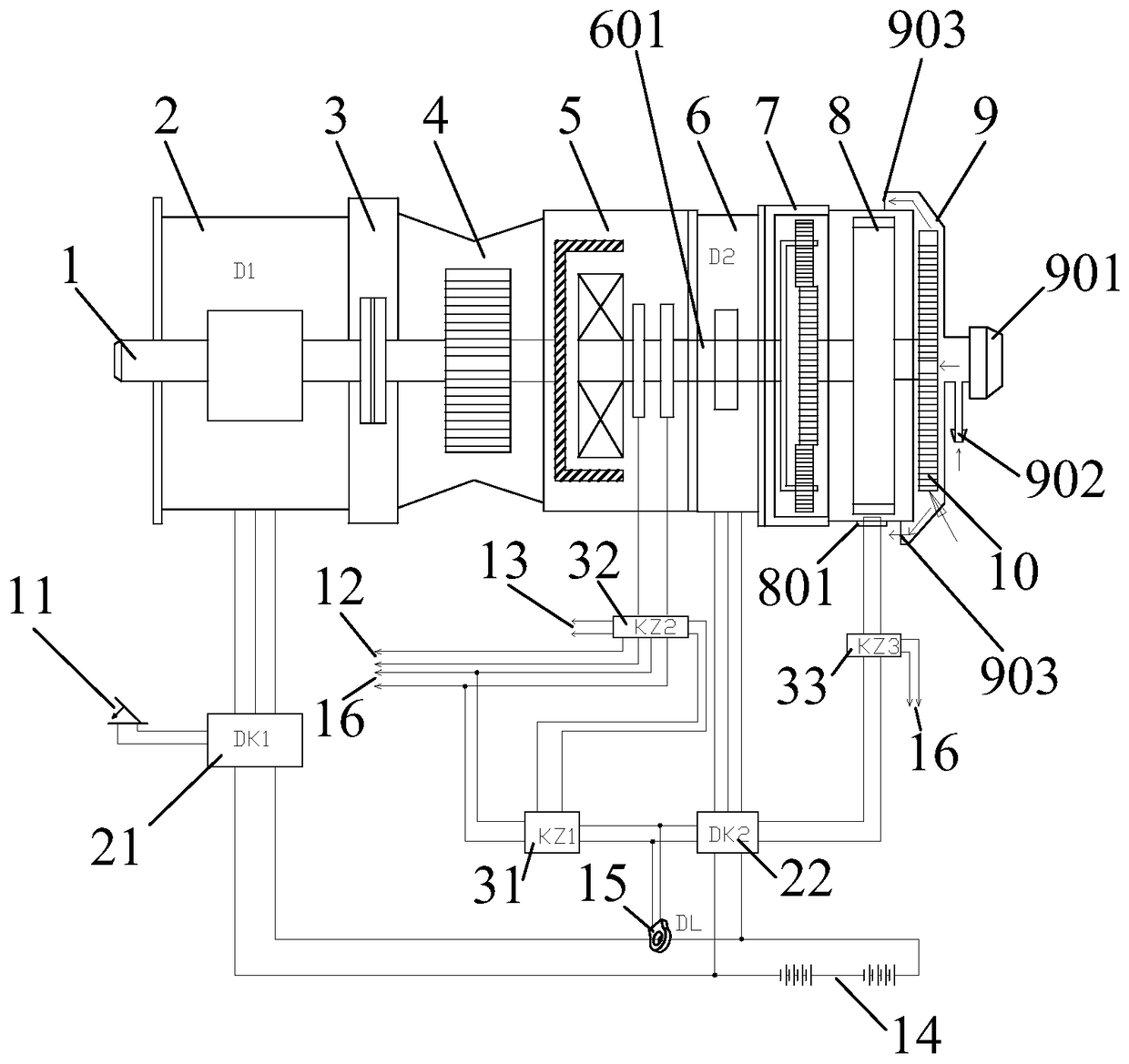
[0043] Such as figure 1 As shown, an electric vehicle power device includes a main power source part, an auxiliary power source part and a flywheel energy storage part.

[0044] The main power source part includes the main drive motor 2, the main drive motor controller 21, the accelerator pedal 11 and the main battery pack 14, the main battery pack provides power to the main drive motor through the main drive motor controller 21, and the accelerator pedal 11 provides operation signals to the main drive motor controller 21 , and the main drive motor controller 21 controls the main drive motor 2 .

[0045]The auxiliary power source part includes an auxiliary drive motor 6, an auxiliary drive motor controller 22, a current sensor 15, a current sensor controller 31, and an electromagnetic slip clutch controller 32. The auxiliary drive motor 6 provides power; the current sensor 15 detects the output current of the aforementioned main battery pack 14, and transmits detection signal...

Embodiment 2

[0066] Such as figure 1 As shown, the second embodiment is a further improvement on the basis of the first embodiment, which mainly adds a vacuum negative pressure generator 9 and a centrifugal fan impeller 10 . The vacuum negative pressure generator 9 is provided with an adjustable air filter 901 , an air inlet 902 and an air outlet 903 . The impeller of the centrifugal fan is placed in the vacuum negative pressure generator 9, and the impeller of the centrifugal fan is coaxially fixed with the flywheel. The air outlet 903 preferably faces the direction of the auxiliary drive motor.

[0067] After using the scheme, the DC vacuum pump configured by the electric vehicle in the prior art can be eliminated, and the service life of the low-voltage battery pack is improved.

[0068] In the prior art, an electric vehicle needs to use some negative pressure equipment, such as a brake system. In order to provide negative pressure, the prior art generally additionally adopts a vacuu...


PUM


Abstract

The invention relates to an electric automobile power device which is applicable to driving of electric automobiles. According to the technical scheme, one end of the output shaft of a main driving motor is fixedly connected with the output shaft of an electromagnetic slip clutch through a coupling (3) and a differential mechanism (4) in sequence; a main driving motor controller (21) is used for controlling operation of a main driving motor; an acceleration petal (11) is used for providing an operation signal to the main driving motor controller; the electromagnetic slip clutch (5) is provided with an input shaft and an output shaft; the electric automobile power device further comprises a current sensor (15), a current sensor controller (31), an electromagnetic slip clutch controller (32), an auxiliary driving motor (6), a lifting gearbox (7), an auxiliary driving motor controller (22), a flywheel (8), a speed detection sensor (801) and a speed detection sensor controller (33). By adoption of the technical scheme, a power device transmission effect is achieved, the multiple of multiplying power discharge of a battery pack can be reduced, and the service life of the battery pack is shortened.

Description

technical field [0001] The invention relates to an electric vehicle power device. The device adopts the combined use of double motors, flywheels and electromagnetic slip clutch structure, which can effectively improve the power transmission effect of electric vehicles and is suitable for driving electric vehicles. Background technique [0002] With the rapid development of the automobile industry, various new energy vehicles are emerging, such as pure electric vehicles. The rate discharge of the battery pack used in pure electric vehicles is a difficult problem, which seriously affects the power output effect of electric vehicles and the life of the battery pack. [0003] In order to improve the life of the battery pack under actual working conditions, some people have proposed the effect of connecting a group of super capacitors in parallel between the series battery packs. For example, Chinese Patent Publication No. CN1833908A discloses a hybrid vehicle, which uses a bat...

Claims


Application Information

Patent Timeline
Patent Type & Authority Patents(China)
IPC IPC(8): B60L11/18B60L11/16B60L15/20B60L15/32B60L7/10B60L50/30
CPCY02T10/70Y02T10/72
Inventor 周伟周金平
Owner 周伟
Learn More