Device for solid-liquid separation and resource recovery of rolling oil sludge and use method of device

A technology for solid-liquid separation and oil sludge rolling, applied in chemical instruments and methods, sludge treatment, process efficiency improvement, etc., can solve the harsh operating conditions of waste lubricating oil regeneration process, secondary pollution of acid residue and alkali residue, investment and high operating costs, to achieve the effects of easy operation and maintenance, high recovery rate, and reduced equipment investment and operating costs

Inactive Publication Date: 2016-11-23
BAOSTEEL STAINLESS STEEL
View PDF6 Cites 20 Cited by
  • Summary
  • Abstract
  • Description
  • Claims
  • Application Information

AI Technical Summary

Problems solved by technology

[0008] Aiming at the problems of harsh operating conditions, high investment and operating costs, long process flow, and secondary pollution of acid slag and alkali slag in the regeneration process of conventional waste lubricating oil, combined with the characteristics of waste oil sludge in rolling mills in the iron and steel industry, a rolling The method and device for solid-liquid separation and resource recovery of oil sludge are characterized in that pla

Method used


Image

  • Device for solid-liquid separation and resource recovery of rolling oil sludge and use method of device
  • Device for solid-liquid separation and resource recovery of rolling oil sludge and use method of device
  • Device for solid-liquid separation and resource recovery of rolling oil sludge and use method of device

Examples


Embodiment 1

[0057] The rolling oil sludge is taken from the DMS20-roll reversible cold rolling unit of a steel enterprise cold rolling plant. The solid phase is 20%, and the oil sludge is dried. It is found that the dry basis components are mainly Fe, Cr, Ni, Mn, Si, and Ca (the sum of the contents is about 60%), and contains traces of Mg, Zn, Pb, P, etc. (the contents are about 60%). and less than 1%). In addition, in the preliminary experiment, it was found that the rolling oil sludge has poor sedimentation property, and the natural sedimentation height in one month is only 10%, and the "solid phase" emulsification "liquid phase" performance at the bottom is good, and the solid-liquid separation is very difficult.

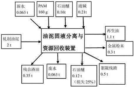
[0058] Take 2 tons of this rolling oil sludge, and carry out solid-liquid separation and resource recovery of oil sludge according to the aforementioned separation method. Regeneration of waste oil through pressure distillation; Finally, using existing equipment, solvent ex...

Embodiment 2

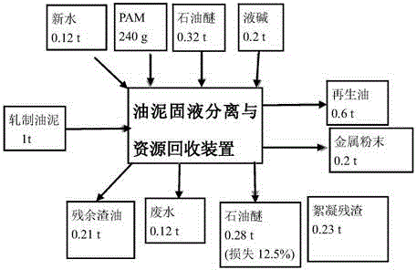
[0075] The rolling oil sludge solid-liquid separation and resource recovery device, method and implementation process are the same as those in Example 1. The difference is the treatment amount of rolling sludge, flocculant, liquid caustic soda and petroleum ether. material balance as image 3 shown.

Embodiment 3

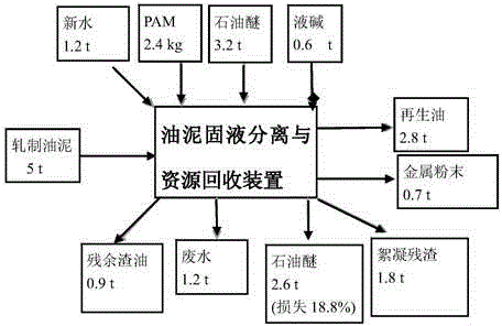
[0077] The rolling oil sludge solid-liquid separation and resource recovery device, method and implementation process are the same as those in Example 1. The difference is the treatment amount of rolling sludge, flocculant, liquid caustic soda and petroleum ether. material balance as Figure 4 shown.


PUM


Abstract

The invention discloses a device for solid-liquid separation and resource recovery of rolling oil sludge and a use method of the device. The device comprises an oil sludge storage tank, a screw pump, a plate-and-frame filter press, a middle tank, an oil pump, a three-in-one reactor, a distillation column, a condenser, a clear oil tank and a vacuum pump, wherein the oil sludge storage tank communicates with the screw pump and the bottom of the three-in-one reactor, the screw pump communicates with the plate-and-frame filter press, the plate-and-frame filter press communicates with the middle tank, the middle tank communicates with the oil pump, the oil pump communicates with the top of the three-in-one reactor, the distillation column is arranged at the top of the three-in-one reactor and communicates with the clear oil tank through the condenser, and the bottom of the clear oil tank communicates with the vacuum pump. The device has the beneficial effects of being simple and reliable in process, convenient to operate, high in pertinence, safe, environment-friendly and suitable for promotion.

Description

technical field [0001] The invention belongs to the technical field of industrial hazardous waste treatment and resource utilization, and relates to a method and a device for solid-liquid separation and resource recovery of rolling sludge. Background technique [0002] In the process of steel rolling, in order to pursue high speed, high efficiency, high quality, reduce power consumption, reduce roll wear, ensure cooling effect, avoid rust and dirt mixing, and stabilize rolling load, it is necessary to choose a suitable lubricating oil. The lubrication system of rolling oil has a direct impact on the production capacity and product quality of the rolling mill. [0003] In order to increase the utilization rate of lubricating oil and ensure the quality of rolled products, the newly-built lubrication systems for multi-roll mills in Hyundai adopt filtering systems with automatic backwashing functions. Take the 20-high rolling mill of Sendzimir stainless steel plate and strip pr...

Claims


Application Information

Patent Timeline
IPC IPC(8): C10M175/00C22B7/00C02F11/00
CPCY02P10/20
Inventor 朱建英石磊
Owner BAOSTEEL STAINLESS STEEL
Why Eureka
Try Eureka