Final covering layer for semi-aerobic landfill

An end-field coverage and quasi-aerobic technology, applied in the direction of smoke removal, cleaning methods and appliances, chemical instruments and methods, etc., can solve problems such as abnormal operation, high cost, and reduced strength of landfills, so as to prevent rainwater from entering, Good air permeability, the effect of promoting methane oxidation

Inactive Publication Date: 2016-12-07
CHINESE RES ACAD OF ENVIRONMENTAL SCI
View PDF8 Cites 11 Cited by
  • Summary
  • Abstract
  • Description
  • Claims
  • Application Information

AI Technical Summary

Problems solved by technology

[0003] The active collection and utilization of landfill gas (LFG) through the pipeline system is the key to controlling CH in domestic waste landfills. 4 An effective method for release; however, the LFG collection and utilization system is expensive, and may not be economically feasible for small and medium-sized landfills; at the same time, the CH of the landfill after closure 4 The intensity of generation is reduced, and the efficiency of the active collection system will also be reduced, and it may even fail to operate normally.

Method used


Image

  • Final covering layer for semi-aerobic landfill
  • Final covering layer for semi-aerobic landfill
  • Final covering layer for semi-aerobic landfill

Examples


Embodiment 1

[0066] The CH of different covering materials and seeding ratio of embodiment 1 4 oxidation rate

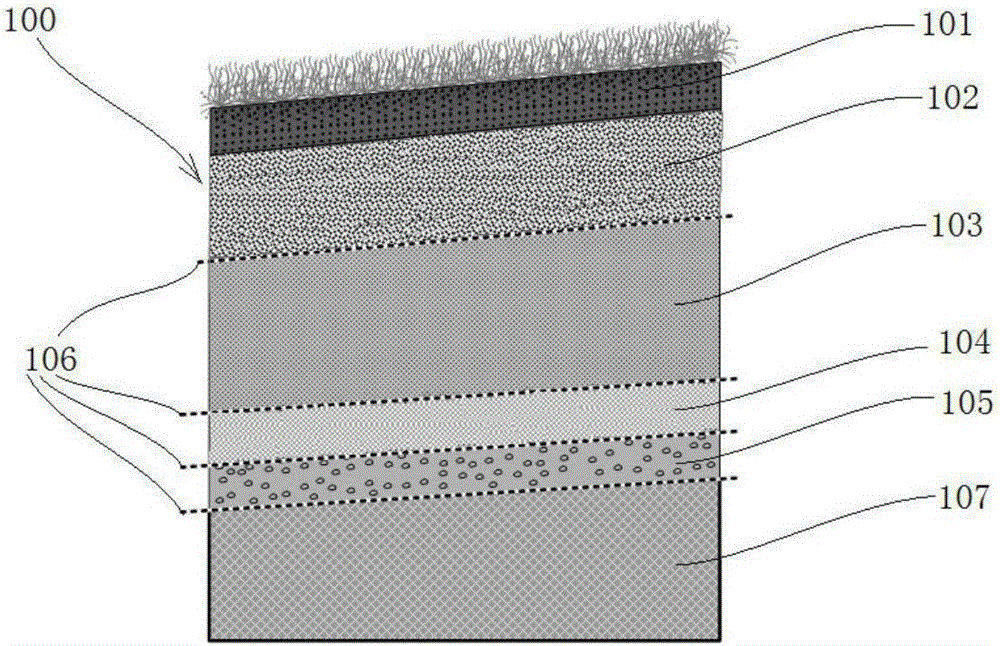
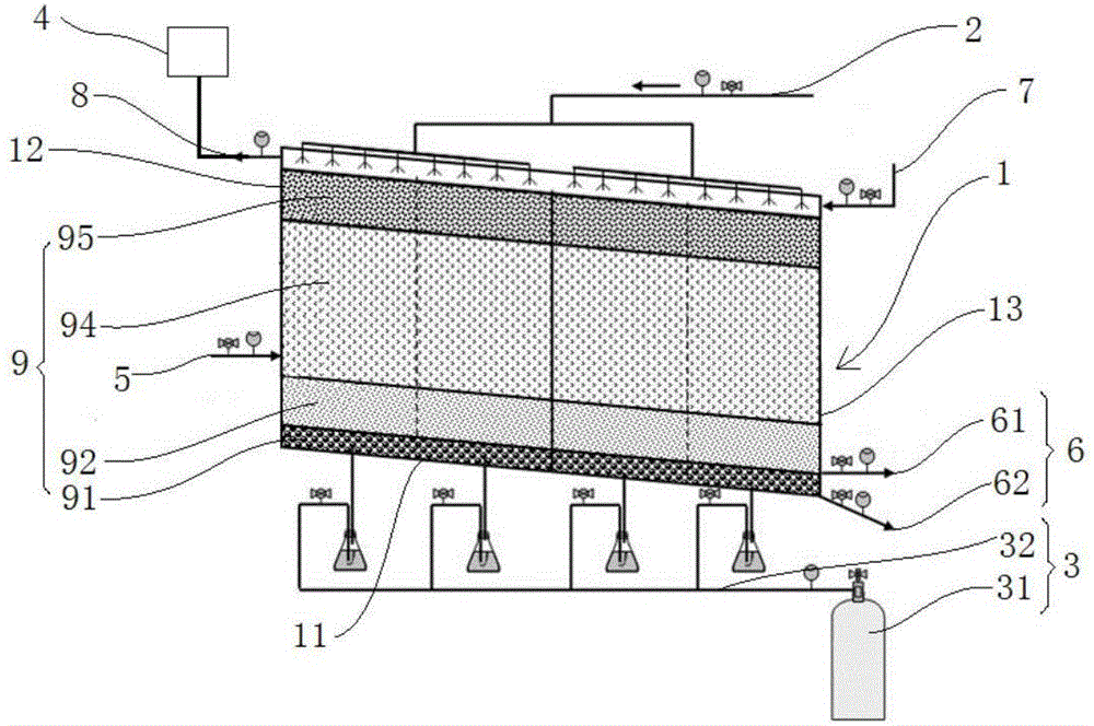
[0067] The overlay methane oxidation simulation device is used, and its schematic diagram is shown in figure 2 As shown, the simulation device includes a closed box, a precipitation system, a methane gas input system, a methane gas detection system, a water inlet, a water outlet, an air inlet and an air outlet. The bottom surface of the closed box includes the first side and the second On the second side opposite to one side, the first side is inclined to the second side, the side wall connected to the first side is the high side 12, and the side wall connected to the second side is the low side 13, laying in the box parallel to Covering layer 9 on the bottom surface of the box body. The covering layers are successively from bottom to top a fine sand layer 91 , a sandy clay layer 92 , a geotextile layer, a loamy sand layer 94 and a biological covering layer 95 . A water inlet...

Embodiment 2

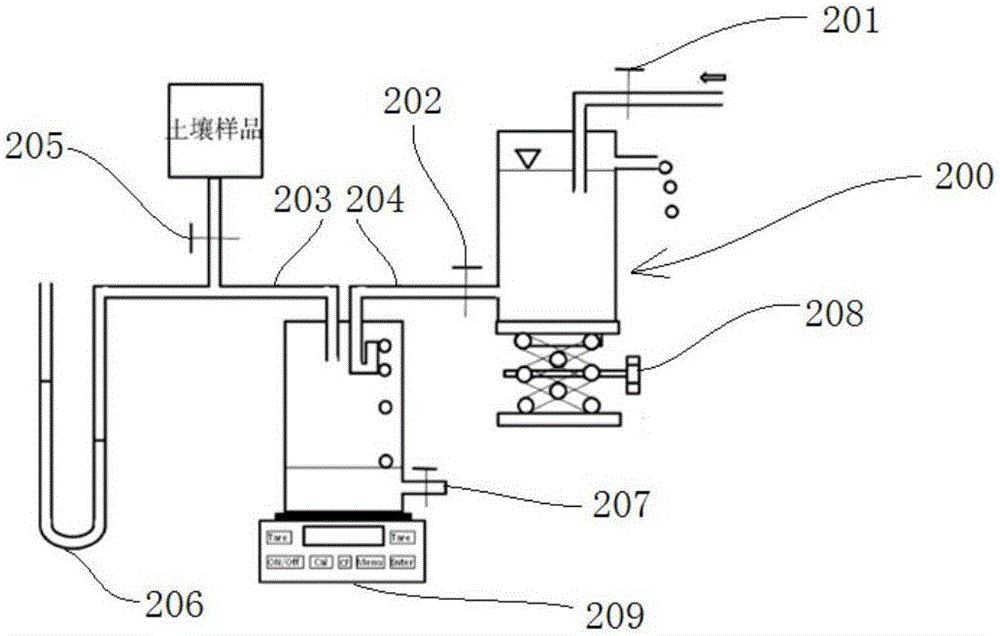
[0075] The gas conduction performance of embodiment 2 final covering layer

[0076] The method of "a simple method for measuring soil air permeability and its application ("Soil", 2014, 46(4):766-768)" proposed by Bi Lidong et al. (2014).

[0077] (1) Measuring principle

[0078] According to Darcy's law, soil air permeability Q is proportional to soil ventilation area S, air pressure difference ΔP, and time Δt, and inversely proportional to soil thickness h and air viscosity coefficient μ, namely:

[0079] Q = K S · Δ P · Δ t h · μ - - - ( 1 )

[0080] In the formula: K is the soil air permeability rate; Q is the soil air permeability; S is the soil air ventilation area; Δ...

Embodiment 3

[0091] Example 3 Overlay drainage performance test

[0092] The simulated equipment in Example 1 is used to study the influence of rainfall intensity on the drainage performance of the covering layer after the selected covering layer structure. The drainage performance experiment of aquifer and capillary barrier layer was carried out under the same conditions by changing the rainfall intensity:

[0093] The specific experimental conditions are: drainage layer, permeability coefficient is 1×10 -4 ~1×10 -3 m / s, thickness 30cm; capillary barrier layer, permeability coefficient 1×10 -6 ~5×10 -6 m / s, thickness is 50cm; aquifer, permeability coefficient is 1×10 -4 ~1×10 - 3 m / s and a thickness of 30cm.

[0094] This study uses the SEEP / W module in GeoStudio software for simulation.

[0095] The simulated slope of the model is 1:3, and the simulated rainfall infiltration intensity is 1×10 -8 , 1×10 -7 , 1×10 -6 , 1×10 -5 , 1×10 -4 , 1×10 -3 , 1×10 -2 and 1×10 -1 m / s. ...


PUM


Abstract

The invention relates to the field of garbage treatment, in particular to a final covering layer for household refuse semi-aerobic landfill. The final covering layer covers the surface layer of a household refuse semi-aerobic landfill and comprises a vegetation layer, a biological covering layer, a reservoir layer, a capillary barrier layer and a drainage layer sequentially from top to bottom. Methane-oxidizing bacteria exist in the biological covering layer. According to the actual situation of the household refuse semi-aerobic landfill process, the covering layer provided by the invention has good air permeability, and it can be guaranteed that external air is diffused into a landfill pile body; and meanwhile, the landfill gases including methane and the like generated when pile body landfill is conducted are diffused outside the pile body from the inside, so that an appropriate oxidation removing environment is provided for the methane released into the air through the covering layer. By adoption of the final covering layer for household refuse semi-aerobic landfill, the methane oxidation efficiency of the final covering layer is improved through optimization design of all the layers.

Description

technical field [0001] The application relates to the field of garbage disposal, in particular, to a quasi-aerobic landfill final covering layer. Background technique [0002] In recent decades, global climate change and ecological problems caused by the greenhouse effect have become a serious threat to human beings. Methane is an important greenhouse gas, and its warming effect is that of CO 2 21 times; CH 4 The combined contribution to the global greenhouse effect reaches 22%. CH 4 It is also one of the fastest growing greenhouse gases in the atmosphere. Therefore, strengthening the CH 4 The control of emissions has become an important aspect of curbing global warming. Traditional CHs such as wetlands and paddy fields 4 In addition to emission sources, with the development of urbanization and the improvement of human living standards, domestic waste landfills have become increasingly important sources of CH 4 release source. It has been reported that CH emissions ...

Claims


Application Information

Patent Timeline
Patent Type & Authority Applications(China)
IPC IPC(8): B08B15/02
CPCB08B15/02
Inventor 岳波黄泽春黄启飞晏卓逸王琪
Owner CHINESE RES ACAD OF ENVIRONMENTAL SCI
Why Eureka
Try Eureka