
Coke gasification process and device

A technology of coke and process, which is applied in the field of coke gasification process and equipment, can solve the problems of high temperature of coke gasification gas rough mouth, failure of waste heat recovery and utilization, and increase of the proportion of inferior coal, so as to achieve high heat recovery efficiency and benefit Graded recovery of waste heat and low energy consumption

Inactive Publication Date: 2016-12-07
SEDIN ENG
View PDF16 Cites 5 Cited by
  • Summary
  • Abstract
  • Description
  • Claims
  • Application Information

AI Technical Summary

Problems solved by technology

With the rapid development of my country's industry, chemical equipment is gradually developing towards high temperature, high pressure, and large-scale development. In particular, coal gasification technology requires a gasification pressure of at least 40 kg, and a daily coal input of 1,000 tons. The reserves of high-quality coal are decreasing, but the proportion of low-quality coal is gradually increasing, especially the proportion of coal with ash melting point greater than 1500 degrees is gradually increasing, which makes the temperature and pressure of gasification gas or subsequent exhaust gas increase accordingly. Patent Name: A high-temperature and high-pressure waste heat boiler, application number: 201110462710.2 The patent solves the problem of high pressure and high temperature, but the heat recovery process and equipment we currently use for fixed-bed gasification: Modern Coal Chemical Technology Manual 2nd Edition, pages 424 to 428 The typical fixed-bed gasification process in Introduction 5 is one-stage heat recovery, which produces one-grade steam. The temperature of the coke gasification gas is high, and the use of the original process not only causes waste of resources, but also pollutes the environment
Patent name: Waste heat boiler for pressurized gas, application number: 200510010273.5 The patent is mainly used to solve the gasification of pulverized coal and improve the efficiency of heat recovery, but it is still a first-level heat recovery, which produces a single-level steam and fails to fully recover waste heat use

Method used


Image

  • Coke gasification process and device
  • Coke gasification process and device
  • Coke gasification process and device

Examples


Embodiment 1

[0042] The crushed coal pressurized gasifier refers to the extension of 2.9 meters on the basis of the fixed bed coal gasifier of 200580041975.8, and the Bosman sleeve adopts a water jacket structure.

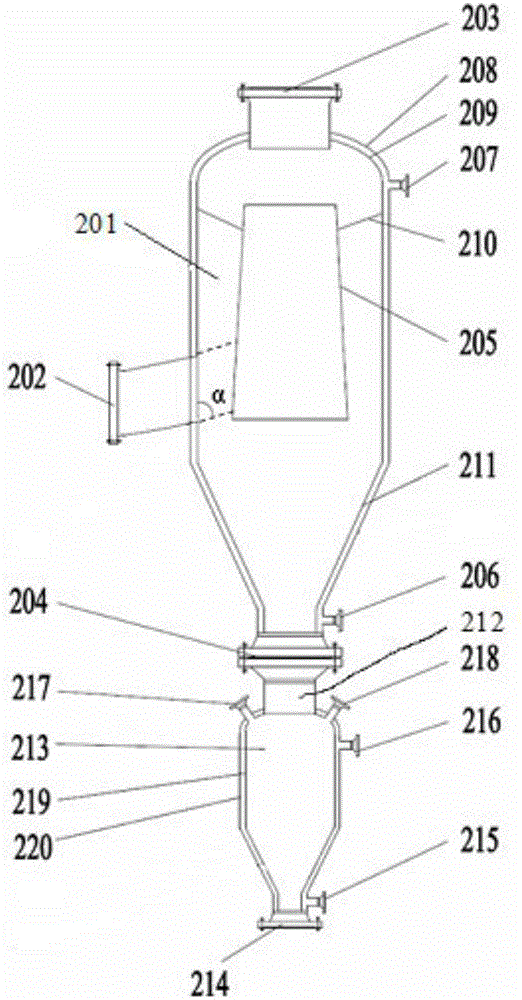
[0043] The dust removal cyclone separator device includes a cyclone dust collector 201 and an ash tank 213. The cyclone dust collector 1 includes an outer cylinder body 211 and an inner cylinder body 205. The upper part of the outer cylinder body 211 is a straight cylinder, the lower part is an inverted cone, and the outer cylinder body 211 is composed of the outer wall 208 of the outer cylinder and the inner wall 209 of the outer cylinder, and forms a jacket structure. The inner cylinder 205 is fixed on the inner wall 209 of the outer cylinder through a stretching member 210. The crude gas inlet 202 containing oil and dust passes through the outer cylinder 211 and The lower part of the inner cylinder 205 is connected, the crude gas outlet 203 is located at the top of the outer ...

Embodiment 2

[0063] The pulverized coal pressurized gasifier refers to CN201410763734.5, which is a kind of pulverized coal pressurized gasifier based on an extension of 1.1 meters, and the Bosman sleeve adopts a water jacket structure.

[0064] The angle α formed between the oily and dusty crude gas inlet 202 and the inner wall 209 of the outer cylinder is 76 degrees. The wall temperature of the inner wall 209 of the outer cylinder and the inner wall 219 of the ash tank is 273°C.

[0065] The cyclone dust collector 201 of the present invention is based on the diameter of 1 m of the inner wall 209 of the outer cylinder, and other structural relative parameters are shown in Table 3.

[0066] Table 3 Design structural parameters of cyclone dust collector

[0067] serial number

structure name

Structural relative parameters (unit m)

1

The inner wall of the outer cylinder is 209 diameter

1.0

2

Oil and dust crude gas inlet 202 position (measured from t...

Embodiment 3

[0075] The crushed coal pressurized gasifier refers to a crushed coal pressurized gasifier described in CN201410763734.5. The height of the crushed coal pressurized gasifier is extended by 2.5 meters, and the Bosman sleeve adopts a water jacket structure.

[0076] The angle α formed between the oily and dusty crude gas inlet 202 and the inner wall 209 of the outer cylinder is 82 degrees. The wall temperature of the inner wall 209 of the outer cylinder and the inner wall 219 of the ash tank is 225°C.

[0077] The cyclone dust collector 201 of the present invention is based on the diameter of 1 m of the inner wall 209 of the outer cylinder, and other structural relative parameters are shown in Table 4.

[0078] Table 4 Design structural parameters of cyclone dust collector

[0079]

[0080]

[0081] (1) Coke is used as raw material to produce crude gas containing oil and dust with a pressure of 1.1MPa and a temperature of 515°C through crushed coal pressurized gasificatio...


PUM


Abstract

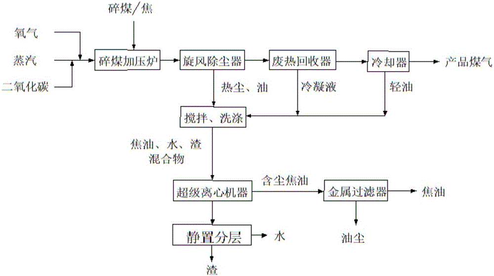
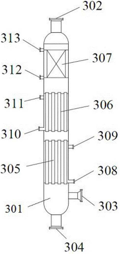
A coke gasification process comprises the steps that coarse coal gas carrying oil-containing dust enters a cyclone separator for separation, separated gas is mixed with the coarse coal gas carrying oil-containing dust entering the cyclone separator, re-separation is performed to obtain coarse coal gas and oil-containing dust; the coarse coal gas enters an integrated waste heat recovery device and sequentially passes through an overheater, a heat recovery device II, a heat recovery device I for staged heat recovery and then is discharged to a cooler through a recovered waste heat and coarse coal gas outlet, and recovery heat generates steam at the three levels of low-pressure saturation, middle-pressure saturation and overheating. The coke gasification process has the advantages that no washing coal gas water is produced, coal gas waste heat can be recycled in a staged mode, and meanwhile different levels of steam are produced.

Description

technical field [0001] The invention belongs to a coke gasification process and equipment. Background technique [0002] Crushed coal pressurized gasifier is a fixed bed coal gasifier, due to the low requirements for raw coal, that is, except for strong caking coal, other coal types can be gasified, especially low-rank coal and high ash melting point Low-quality coal and gasification coke. The gasifier is widely used in coal-to-synthetic ammonia, methanol, dimethyl ether, synthetic oil and coal gas. However, the crushed coal pressurized gasification technology used in the crushed coal pressurized gasification process currently in industrial operation is suitable for gasifying coal with carbonization and drying layers. During the gasification process, heat is absorbed during drying and carbonization, and the temperature at the top of the gasifier It will not exceed the withstand temperature of the gasifier material. In addition, the reactivity of coke is poor. Entrained bed...

Claims


Application Information

Patent Timeline
IPC IPC(8): C10J3/20C10J3/84C10J3/72
CPCC10J3/20C10J3/72C10J3/84C10J2300/0936C10J2300/1696C10J2300/1884Y02P20/129
Inventor 周恩利李晓崔晓曦左永飞刘丰力杨伟
Owner SEDIN ENG
Learn More