
Preparation method of graphite/carbon nano-tube array composite heat conducting film

A carbon nanotube and thermally conductive film technology, applied in nanotechnology and other directions, can solve the problems of large changes, reduced specific surface area, easy agglomeration, etc., to reduce the interface thermal resistance, increase the radiation area, and improve the heat transfer effect.

Active Publication Date: 2016-12-14
SHANGHAI JIEYUAN ENVIRONMENTAL SCI & TECH
View PDF11 Cites 5 Cited by
  • Summary
  • Abstract
  • Description
  • Claims
  • Application Information

AI Technical Summary

Problems solved by technology

However, this material has the following defects: carbon nanotubes and graphite sheets are connected only by surface adhesion, and the integrity and continuity of the final product are poor; The specific surface area is reduced, and the effective radiation area cannot be increased; the carbon nanotubes are randomly distributed, and the directionality is poor, and the heat cannot be conducted and diffused in the preset direction
In the existing preparation methods of graphite and carbon nanotube composite film materials, the coating method and the full wet filtration method cannot form a highly oriented composite of carbon nanotube arrays and graphite film due to the randomness of the distribution caused by the dispersion of carbon nanotubes. thin film material; while the random distribution of vapor-deposited carbon nanotube particles causes the non-orientation of carbon nanotubes, and it is also impossible to form a composite thin film material of highly oriented carbon nanotube arrays and graphite film
This means that none of the above materials can greatly increase the effective radiation area, so the heat cannot be quickly and directionally diffused to the surrounding environment such as air.
In addition, the existing composite film materials of graphite and carbon nanotubes all introduce carbon nanotubes on the basis of the formed graphite film. The process is relatively complicated, and the original production equipment has been greatly modified, which is not conducive to continuous production.

Method used


Image

  • Preparation method of graphite/carbon nano-tube array composite heat conducting film
  • Preparation method of graphite/carbon nano-tube array composite heat conducting film

Examples


Embodiment I

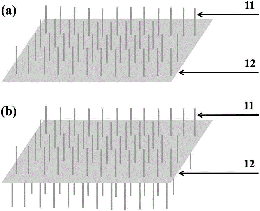
[0028] Such as figure 1 As shown in (a), a graphite / carbon nanotube array composite heat-conducting film includes: a graphite film 12 and a carbon nanotube array vertically grown on the upper surface of the graphite film, wherein the thickness of the graphite film can be 10-100 μm, and the nanocarbon The thickness of the tube array can be 1-200 μm. In this specific embodiment, the thickness of the graphite film is 100 μm, and the thickness of the carbon nanotube array is 200 μm.

Embodiment II

[0030] Such as figure 1 As shown, a graphite / carbon nanotube array composite heat-conducting film includes: graphite film 12 and carbon nanotube arrays grown vertically on the upper surface and the lower surface of the graphite film, wherein the thickness of the graphite film can be 10-100 μm, and the nanocarbon The thickness of the tube array can be 1-200 μm. In this specific embodiment, the thickness of the graphite film is 10 μm, and the thickness of the carbon nanotube array is 1 μm.

[0031] Preferably, the graphite film and the carbon nanotube array are produced by a one-step method.

[0032] A specific implementation of a method for preparing a carbon nanotube array / graphite composite thermally conductive film is as follows:

Embodiment 1

[0034] In this example, iron is used as a catalyst, and its loading implementation process is as follows:

[0035] One of the surfaces of the graphite film is loaded with an iron catalyst layer by magnetron sputtering technology; the graphite film is placed in the constant temperature zone of the vapor deposition furnace, and the graphite film is placed in the reducing atmosphere Ar / H 2 Under the program, the temperature was raised to 400 ° C and kept for 2 hours, and the reduction treatment of the catalyst was carried out, wherein Ar / H 2 The flow rate is 900mL / min, H 2 The volume fraction is 20%.

[0036] After the temperature is programmed to 800°C, switch the gas to carbon source gas C 2 h 4 / Ar / H 2 Keep for 2h, deposit the carbon nanotube array, switch to the reducing atmosphere Ar / H after the end 2 and down to room temperature, where C 2 h 4 / Ar / H2 The flow rate is 900mL / min, C 2 h 4 and H 2 The volume fraction is 25%.

[0037] Then, graphitization treatment i...


PUM

PropertyMeasurementUnit
Thicknessaaaaaaaaaa
Thicknessaaaaaaaaaa
Thicknessaaaaaaaaaa

Abstract

The invention relates to a preparation method of a graphite / carbon nano-tube array composite heat conducting film. The preparation method comprises the following steps: (1) supporting a catalyst layer or a catalyst precursor layer on the surface of a graphite film; (2) placing the graphite film in chemical vapor deposition equipment, depositing carbon nano-tube arrays after carrying out reduction treatment to obtain a heat conducting graphite film of which the surface is deposited with the carbon nano-tube arrays; (3) carrying out graphitization on the heat conducting graphite film of which the surface is deposited with the carbon nano-tube arrays to obtain the graphite / carbon nano-tube array composite heat conducting film. According to the invention, a special method of depositing the highly oriented carbon nano-tube arrays on the surface is adopted, so that the effective radiation area of the heat conducting graphite film is obviously increased, and the interfacial thermal resistance between the conducting film and air is reduced to obviously improve the heat transfer rates of the heat conducting film with surrounding environments such as the air per unit area to rapidly diffuse heat from the heat conducting film to the surrounding environments such as air.

Description

technical field [0001] The invention belongs to the technical field of heat conduction and heat dissipation, and relates to a preparation method of a graphite / carbon nanotube array composite heat conduction film. Background technique [0002] In recent years, graphite film materials have been widely used in technical fields such as heat dissipation of electronic products, heat-resistant sealing materials, and heating elements due to their excellent high thermal conductivity, heat resistance, corrosion resistance, and high electrical conductivity. Graphite film with high thermal conductivity is widely used in handheld terminals such as smartphones and tablet computers with dense electronic components and high heat generation, and realizes heat dissipation through high thermal conductivity. [0003] At present, by directly carbonizing and graphitizing organic polymer film materials, graphite film materials with high thermal conductivity, high electrical conductivity, and bendi...

Claims


Application Information

Patent Timeline
IPC IPC(8): C01B31/04C01B31/02B82Y40/00
CPCC01P2004/20C01P2006/32
Inventor 葛翔朱秀娟李志文林剑峰
Owner SHANGHAI JIEYUAN ENVIRONMENTAL SCI & TECH
Learn More