Substrate surface microfluidics method

A substrate surface, microfluidic technology, applied in the process of producing decorative surface effects, chemical instruments and methods, microstructure technology, etc., can solve the problems of difficult to achieve precise control of liquids, development bottlenecks, etc. The effect of convenience, overcoming harsh requirements, and breaking through the bottleneck of development

Inactive Publication Date: 2016-12-21
SHANGHAI UNIV
View PDF7 Cites 5 Cited by
  • Summary
  • Abstract
  • Description
  • Claims
  • Application Information

AI Technical Summary

Problems solved by technology

However, the method also has obvious defects. The main problem is that it is difficult to realize the precise control of the liquid by the traditional method, which has become the bottleneck of the development of this method.

Method used


Image

  • Substrate surface microfluidics method
  • Substrate surface microfluidics method
  • Substrate surface microfluidics method

Examples


Embodiment 1

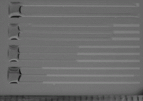
[0038] In this example, see figure 1 , a method for substrate surface microfluidics, comprising the steps of:

[0039] a. Select a silicon wafer as the substrate, and use hydrophobic substances as modifiers to modify the surface of the substrate. The specific steps are as follows: first, the silicon wafer is ultrasonically treated with chloroform, acetone, ethanol, and water for 10 minutes, and then blown dry with nitrogen for later use; prepare chloroform : The molar ratio of n-ethane is 40ml of the mixed solution of 3:7, then add OTS 10ul, after stirring evenly, the modifier is obtained, put the spare silicon substrate after the above treatment into the modifier, and let it stand in the fume hood for 5 -7 hours, after taking the silicon wafer out of the modifier, rinse the silicon wafer with chloroform, acetone, and ethanol respectively, blow dry the silicon wafer with nitrogen, and then bake the silicon wafer at 80°C for 10 minutes. A modified surface layer is formed on th...

Embodiment 2

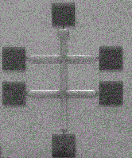
[0044] This embodiment is basically the same as Embodiment 1, especially in that:

[0045] In this example, see figure 2 , a method for substrate surface microfluidics, comprising the steps of:

[0046] a. Select glass as the substrate, use hydrophobic substances as modifiers, and modify the surface of the substrate, specifically: first, ultrasonically treat the glass with chloroform, acetone, ethanol, and water for 10 minutes, and then dry it with nitrogen for later use; prepare chloroform: Add 40ml of a mixed solution with a molar ratio of ethane of 3:7, add OTS 10ul, stir well to obtain a modifier, put the spare glass substrate after the above treatment into the modifier, and let it stand in a fume hood for 5-7 hours , after taking the glass out of the modifier, rinse the glass with chloroform, acetone, and ethanol respectively, blow the glass dry with nitrogen, and then bake the silicon wafer at 80°C for 10 minutes to form a modified surface layer on the glass surface. ...

Embodiment 3

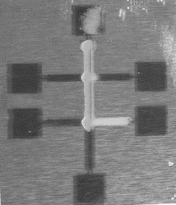
[0051] This embodiment is basically the same as the previous embodiment, and the special features are:

[0052] In this example, see image 3 , a method for substrate surface microfluidics, comprising the steps of:

[0053] a. This step is identical with embodiment two;

[0054] B. this step is identical with embodiment two;

[0055] c. Utilize the method of electric heating, select the electric current to control the heating method, through the electric selection area, make the part of the gold pattern on the hydrophobic substrate be connected with the external circuit, form the external circuit system, and apply it to the hydrophobic substrate by controlling the external circuit system The current of the gold pattern on the hydrophobic substrate is heated locally, and the other regions of the gold pattern on the hydrophobic substrate that are not energized are not heated by electricity and have a lower temperature. The local temperature change of the gold pattern is used ...


PUM


Abstract

The invention discloses a substrate surface microfluidics method. The method comprises the following steps: performing modification treatment on a substrate; making a pre-pattern of liquid flow on the surface of the substrate; making a solvent flow along the pattern according to a hydrophilicity and hydrophobicity principle; controlling the solvent to flow directionally by an electrical heating method; and conveying and diluting solvent-doped dye molecules directionally. Another measure of a microfluidic technology is provided by the method. Selective flow of the liquid can be realized through a hydrophilic and hydrophobic surface pattern; the flow speed of the liquid can be controlled by controlling different line widths of the hydrophilic and hydrophobic surface pattern; surface microfluidics can be realized through electrical region-based heating; and organic functional molecules can be conveyed directionally through surface microfluidics. Through adoption of the method, strict requirements of a conventional preparation process are eliminated; the bottleneck in development of a conventional surface microfluidics technology is broken; and the requirements on instruments and the environment are relatively low.

Description

technical field [0001] The invention relates to a method for preparing a microstructure device, in particular to a method for surface microfluidics, which is applied in the technical field of preparation of microstructure devices. Background technique [0002] Microfluidic technology refers to the technology of processing or manipulating tiny fluids by manufacturing micropipes in the base, while surface microfluidic refers to the realization of microfluidic technology on the surface of the base by processing the surface of the base. [0003] In recent years, the micro-total analysis system has transferred the functions of the analysis laboratory to portable analysis equipment or chips to the greatest extent, which greatly saves research costs, improves the accuracy of experimental analysis, and realizes the personalization of the analysis system. And home use, the microfluidic technology known as "lab-on-a-chip" is the fastest growing and most promising field in China. Surf...

Claims


Application Information

Patent Timeline
Patent Type & Authority Applications(China)
IPC IPC(8): B81C1/00B01L3/00
CPCB81C1/00015B01L3/00
Inventor 王海王文冲阚俊杰吴明红雷勇
Owner SHANGHAI UNIV
Why Eureka
Try Eureka