In-furnace denitrification method and device

A technology for denitrification and furnace, which is applied in the direction of combustion method, combustion with various fuels, combustion with block fuel and liquid fuel, etc., which can solve the problem of furnace slagging, desulfurization efficiency, combustion efficiency and burnout rate, which are difficult to guarantee and cannot Extensive promotion and use and other issues to achieve the effect of high denitrification rate, high efficiency and low cost denitrification, and broad market application prospects

Inactive Publication Date: 2017-01-11
HUNAN UNIV OF TECH +1
View PDF7 Cites 2 Cited by
  • Summary
  • Abstract
  • Description
  • Claims
  • Application Information

AI Technical Summary

Problems solved by technology

[0013] Although the above patents have proposed some methods of denitrification during coal-water slurry combustion, there are still problems such as large equipment investment and operating costs, reduced combustion efficiency, slagging in the furnace, and high-temperature corrosion; and there is no corresponding combustion equipment and its control technology. The denitrification and reduction reaction in the furnace cannot reach the ideal state, and it is difficult to guarantee the desulfurization efficiency, combustion efficiency and burnout rate, and it cannot be widely promoted and used at present.

Method used


Image

  • In-furnace denitrification method and device

Examples


Embodiment 1

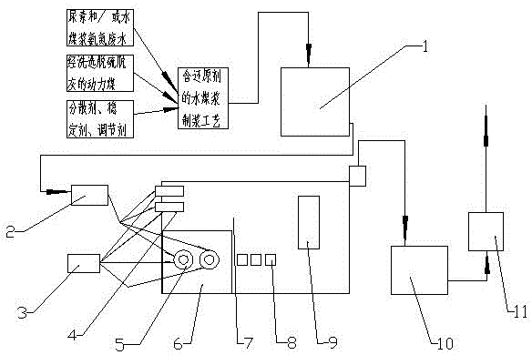
[0044] From attached figure 1 It can be seen that the present invention relates to a kind of coal-water slurry pulping and combustion system integrated equipment for denitrification in the furnace, including a coal-water slurry combustion boiler, which is divided into a main combustion chamber 7 and a secondary combustion chamber 6; , the upper side of the head of the main combustion chamber 7 is equipped with an axial swirling main burner 4, the lower side is a secondary combustion chamber 6, and the side of the secondary combustion chamber 6 is equipped with a secondary burner 5, and the axial swirling main burner 4 It is perpendicular to the auxiliary burner 5 in the axial direction; the axial swirl main burner 4 and the auxiliary burner 5 are respectively connected to the coal-water slurry tank 1 through the screw pump 2 through pipelines, and at the same time, the axial swirl main burner 4 and the The auxiliary burner 5 is connected to the air compressor 3 through pipes a...

Embodiment 2

[0052] The principle of the second embodiment is the same as that of the first embodiment, but the structure is different; a coal-water slurry slurry and combustion system integrated equipment for denitrification in the furnace, including a coal-water slurry combustion boiler, a coal-water slurry combustion boiler Divided into a main combustion chamber 7 and an auxiliary combustion chamber 6; wherein, the main combustion chamber 7 is equipped with an axial swirl main burner 4 on the upper side of the head, and an auxiliary combustion chamber 6 on the lower side, and an auxiliary combustion chamber 6 is arranged on the side. The burner 5, and the axial swirling main burner 4 and the auxiliary burner 5 are perpendicular to each other in the axial direction; the axial swirling main burner 4 and the auxiliary burner 5 pass through the screw pump 2 and the coal-water slurry tank 1 respectively through pipelines At the same time, the axial swirling main burner 4 and the auxiliary bur...

Embodiment 3

[0058] The principle of the second embodiment is the same as that of the first embodiment, but the structure is different; a coal-water slurry slurry and combustion system integrated equipment for denitrification in the furnace, including a coal-water slurry combustion boiler, a coal-water slurry combustion boiler Divided into a main combustion chamber 7 and an auxiliary combustion chamber 6; wherein, the main combustion chamber 7 is equipped with an axial swirling main burner 4 on the upper side of the head, and an auxiliary combustion chamber 6 on the lower side, and an auxiliary combustion chamber 6 is arranged on the side. The burner 5, and the axial swirling main burner 4 and the auxiliary burner 5 are perpendicular to each other in the axial direction; the axial swirling main burner 4 and the auxiliary burner 5 pass through the screw pump 2 and the coal-water slurry tank 1 respectively through pipelines At the same time, the axial swirling main burner 4 and the auxiliary ...


PUM


Abstract

The invention discloses an in-furnace denitrification coal water slurry making and combusting system integrated method and equipment. The method comprises the following steps: on the basis of the traditional slurry making process, adding a denitrification reducing agent, and preparing coal water slurry fuel containing the denitrification reducing agent; spraying the coal water slurry fuel into a boiler for burning, controlling the combustion temperature of the hearth to be stabilized in an optima reduction reaction temperature range and controlling the oxygen content of the flue gas, so that high-efficiency low-cost in-furnace SNCR denitrification of the coal water slurry is realized. The whole device comprises a coal water slurry combustion boiler, wherein the coal water slurry combustion boiler adopts the design of a primary combustion chamber and a secondary combustion chamber and is respectively provided with an axial cyclone primary combustor and a secondary combustor; a fire barrier is arranged at the tail of the primary combustion chamber, an air door is arranged below the primary combustion chamber, the rear upper part of the primary combustion chamber is connected with a dust remover through a pipeline, and the combusted smoke dust is discharged through an induced draft fan connected with the dust remover; and the axial cyclone primary combustor and the secondary combustor are respectively connected with a coal water slurry tank through a screw pump via pipelines, and are also respectively connected with an air compressor at the coal water slurry inlet through pipelines.

Description

technical field [0001] The invention relates to a method and equipment for denitrification of coal-water slurry, in particular to a method and equipment for integrated treatment of coal-water slurry denitrification in a furnace and a combustion system, belonging to the technical field of coal-water slurry combustion. Background technique [0002] Coal-water slurry is a low-pollution, high-efficiency, pipeline-transportable coal-based fluid fuel that emerged in the 1970s. It is made of about 65% coal, about 34% water and about 1% chemical additives. It is processed through a certain process. Its ash and sulfur content are low, the temperature of the flame center is low during combustion, and the combustion efficiency is high. Soot, SO 2 and NO X Emissions are lower than fuel and coal combustion. At present, coal-water slurry technology has been listed as a key promotion technology for energy development in my country, and it is also one of the key technologies for the prio...

Claims


Application Information

Patent Timeline
Patent Type & Authority Applications(China)
IPC IPC(8): C10L10/00C10L1/32F23K1/00F23C3/00F23C5/08
CPCC10L1/326C10L10/00C10L2290/54F23C3/00F23C5/08F23K1/00
Inventor 刘建文陈楠黄敦辉
Owner HUNAN UNIV OF TECH
Why Eureka
Try Eureka