Solar-powered airplane wing and manufacturing method thereof

A technology for a solar-powered aircraft and a manufacturing method, applied in the field of solar cells, can solve the problems of reducing the load of the solar-powered aircraft, difficult to adapt to the wing fit, large mass, etc., so as to improve the flight aerodynamic performance and reliability, improve the conformal effect and Effects of surface smoothness, good flexibility and bendability

Active Publication Date: 2017-02-08
48TH RES INST OF CHINA ELECTRONICS TECH GROUP CORP
View PDF9 Cites 8 Cited by
  • Summary
  • Abstract
  • Description
  • Claims
  • Application Information

AI Technical Summary

Problems solved by technology

Traditional rigid solar cell modules generally use PET light-transmitting film (about 200 μm thick) + EVA layer (about 500 μm thick) + monocrystalline silicon wafer or polycrystalline silicon wafer (about 180 μm thick) + TPE backlight, and its surface density is usually 2.0~ 2.5 kg / m 2 , leading to the lack of flexibility of the solar cell module, and its own mass, not only cannot adapt to the fit with the airfoil surface, but also reduces the load of the solar aircraft, and it is difficult to meet the application requirements of the solar aircraft
[0004] At present, in the disclosed solar UAV wing preparation technology, such as CN 203659894 U and CN201510680597, rigid solar cells are used to prepare solar cell components, in order to ensure that the rigid solar cells in the cell components do not crack during bending , the component cannot undergo large bending deformation, and it is difficult to adapt to the fit of the large curvature change on the wing
Moreover, the laying and installation process of the solar cell module and the wing frame in these patents is complicated, and the installation structure is difficult to meet the high smoothness of the wing surface required by the aerodynamics of the UAV.
In addition, although the surface density of the CN 203659894 U patent is 35% lower than that of traditional solar cell modules, the surface density still reaches 1.2Kg / m 2 At the same time, the solar cell modules prepared in this patent lack a flexible support substrate, which makes it difficult to ensure the commonality between the solar cell modules and the UAV wing frame and the reliability of the solar cells

Method used


Image

  • Solar-powered airplane wing and manufacturing method thereof
  • Solar-powered airplane wing and manufacturing method thereof
  • Solar-powered airplane wing and manufacturing method thereof

Examples


Embodiment 1

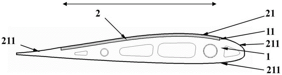
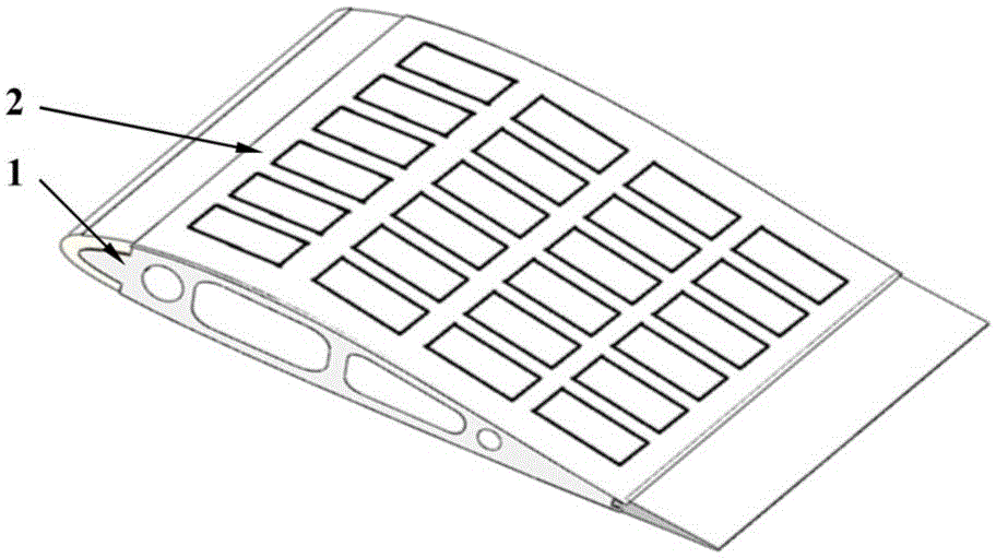
[0045] Such as figure 1 and figure 2 As shown, the solar aircraft wing of the present embodiment includes a wing frame 1 and a flexible solar cell assembly 2, the middle part of the upper surface of the wing frame 1 is provided with a groove 11, and the flexible solar cell assembly 2 includes an encapsulation skin 21 and a device. The component framework 22 on the lower surface of the package skin 21, the component framework 22 is located in the groove 11, and the package skin 21 is along the wingspan direction of the wing frame 1 (such as figure 1 (shown by the arrow) extends outwards to form a wrapping edge 211 , and the wrapping edge 211 wraps on the wing frame 1 . That is, the surface skin of the flexible solar cell module 2 extends to the surface skin of the wing frame 1. This structure greatly improves the conformal effect of the solar cell module and the wing frame and the surface smoothness of the wing, and greatly improves the solar energy. Flight aerodynamic perfo...


PUM


Abstract

The invention discloses a solar-powered airplane wing and a manufacturing method thereof. The solar-powered airplane wing comprises a wing framework and a flexible solar cell module, wherein the middle part of the upper surface of the wing framework is provided with a groove; the flexible solar cell module comprises a packaging skin and an assembly framework arranged on the lower surface of the packaging skin; the assembly framework is arranged in the groove; the packaging skin extends outwards along the two sides of the wing framework in the spanwise direction to form a coating side; and the coating side is coated on the wing framework. The manufacturing method comprises the following steps: S1: preparing the wing framework; S2: preparing the flexible solar cell module; and S3: assembling. The solar-powered airplane wing has the advantages of favorable conformal effects between the solar cell module and wing framework, high surface smoothness, excellent aerodynamic performance, light weight and the like. The preparation method has the advantages of convenient assembly, weight reduction and favorable reliability.

Description

technical field [0001] The invention belongs to the technical field of solar cells, and in particular relates to a solar-powered aircraft wing and a manufacturing method thereof. Background technique [0002] High-altitude and long-endurance solar-powered drones have the advantages of high flight altitude, long working hours, wide coverage, flexible use, low operating costs, and no environmental pollution. The platform has a very broad application prospect. It uses solar radiation energy as power to continuously fly unmanned aerial vehicles at high altitudes for long periods of time. It uses photovoltaic cells to convert solar energy into electrical energy, and drives propellers to rotate through electric motors to generate flight power. During the day, solar-powered UAVs rely on solar cells laid on the surface of the body to convert absorbed solar radiation into electrical energy, maintain the operation of the power system, avionics and payloads, and charge the secondary p...

Claims


Application Information

Patent Timeline
Patent Type & Authority Applications(China)
IPC IPC(8): B64C3/00H01L31/048H01L31/042H01L31/18B64F5/00
CPCB64C3/00H01L31/042H01L31/0445H01L31/048H01L31/18Y02E10/50Y02P70/50
Inventor 周洪彪张建国杨晓生黄齐鸣
Owner 48TH RES INST OF CHINA ELECTRONICS TECH GROUP CORP
Why Eureka
Try Eureka