Ceramic drilling method of composite nanosecond-picosecond-femtosecond laser technology

A technology of femtosecond laser and drilling method, which is applied in the direction of laser welding equipment, welding/welding/cutting items, manufacturing tools, etc., can solve the problems of short electrode life, slow EDM speed, limited ceramic aperture, etc., to achieve High processing efficiency, improving processing accuracy and processing quality, improving processing accuracy and processing efficiency

Active Publication Date: 2017-02-22
GUANGDONG UNIV OF TECH
View PDF6 Cites 39 Cited by
  • Summary
  • Abstract
  • Description
  • Claims
  • Application Information

AI Technical Summary

Problems solved by technology

The ceramic hole processing methods mainly include the following three types: (1) The traditional mechanical drilling method not only limits the ceramic aperture, but also tends to produce cracks on the processing surface and hole wall of the ceramic material, which makes the workpiece scrap; (2) EDM method, because the ceramic material is usually non-conductive, so it is necessary to modify the ceramic, and the EDM speed is slow, the electrode life is short, the efficiency of processing micropores is low, and the cost is high; (3) laser processing method, because the laser has high energy Density and easy to guide and focus, through heat scattering, the material can be melted and evaporated in an instant, realizing non-contact processing with the workpiece, avoiding problems such as tool

Method used


Image

  • Ceramic drilling method of composite nanosecond-picosecond-femtosecond laser technology
  • Ceramic drilling method of composite nanosecond-picosecond-femtosecond laser technology
  • Ceramic drilling method of composite nanosecond-picosecond-femtosecond laser technology

Examples


Embodiment 1

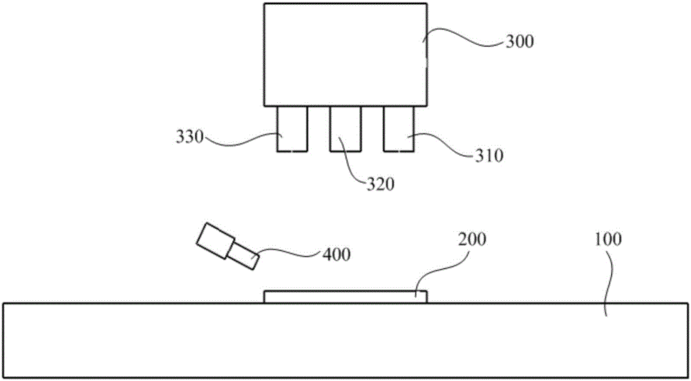
[0039] use as figure 2 The ceramic drilling system of the shown compound nanosecond-picosecond-femtosecond laser technology processes and drills the ceramic workpiece of the present embodiment, and the drilling method is as follows:

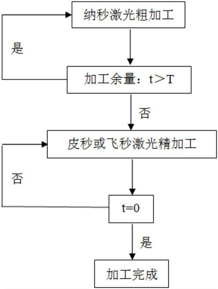
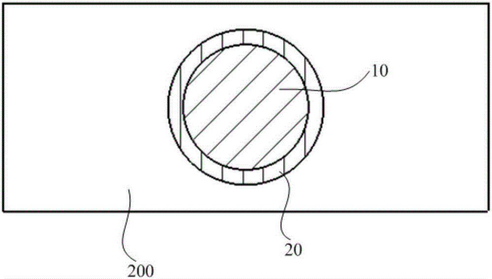
[0040] The ceramic workpiece 200 to be processed is ground and polished, and placed in alcohol for ultrasonic cleaning for 15 minutes. Take it out and fix it on the workbench 100, and adjust the focus of the workbench 100 and the multi-pulse width fiber laser 300 to complete the focus and determine the processing position, such as image 3 As shown, a rough machining area 10 and a finishing area 20 are determined. According to the processing accuracy requirements of the ceramic workpiece 200, the nanosecond laser 310 is used for rough processing first, and the processing path is the helix 1, and the finishing allowance T is reserved according to the data of the dimensional precision measuring instrument, and at the same time, the auxiliary gas ...

Embodiment 2

[0042] use as figure 2 The ceramic drilling system of the shown compound nanosecond-picosecond-femtosecond laser technology processes and drills the ceramic workpiece of the present embodiment, and the drilling method is as follows:

[0043] The ceramic workpiece 200 to be processed is ground and polished, and placed in acetone for ultrasonic cleaning for 30 minutes. Take it out and fix it on the workbench 100, and adjust the focus of the workbench 100 and the multi-pulse width fiber laser 300 to complete the focus and determine the processing position, such as image 3As shown, a rough machining area 10 and a finishing area 20 are determined. According to the processing accuracy requirements of the ceramic workpiece 200, the nanosecond laser 310 is used for rough processing first, and the processing path is a number of first concentric circles 1' from the outside to the inside, and the finishing allowance T is reserved according to the data of the dimensional precision meas...

Embodiment 3

[0045] use as figure 2 The ceramic drilling system of the shown compound nanosecond-picosecond-femtosecond laser technology processes and drills the ceramic workpiece of the present embodiment, and the drilling method is as follows:

[0046] The ceramic workpiece 200 to be processed is ground and polished, and placed in acetone for ultrasonic cleaning for 30 minutes. Take it out and fix it on the workbench 100, and adjust the focus of the workbench 100 and the multi-pulse width fiber laser 300 to complete the focus and determine the processing position, such as image 3 As shown, a rough machining area 10 and a finishing area 20 are determined. According to the processing accuracy requirements of the ceramic workpiece 200, the nanosecond laser 310 is used for rough processing first, and the processing path is a number of first concentric circles 1' from the outside to the inside, and the finishing allowance T is reserved according to the data of the dimensional precision mea...


PUM


Abstract

The invention discloses a ceramic drilling method of a composite nanosecond-picosecond-femtosecond laser technology. The ceramic drilling mechanism of the composite nanosecond-picosecond-femtosecond laser technology comprises the following steps: S10, providing multi-pulse-width fiber laser devices which comprise a nanosecond laser device, a picosecond laser device and a femtosecond laser device, roughly machining a ceramic workpiece fixed on a working table by using the nanosecond laser device, and meanwhile, spraying auxiliary gas at a position nearby a machining position; S20, carrying out finish machining on the ceramic workpiece which is machined roughly by using the picosecond laser device or the femtosecond laser device, and meanwhile, spraying auxiliary gas at a position nearby the machining position; and S30, presetting allowance for finish machining T, detecting residual allowance for machining t by using a dimension precision measurement instrument, repeating the step S10 when t is greater than T, repeating the step S20 when t is greater than 0 and smaller than or equal to T, and repeating in such a way until t is equal to 0. The auxiliary gas is sprayed at the position nearby the machining position, after rough machining by nanosecond laser, finish machining is implemented by picosecond or femtosecond laser, and therefore, machining precision and machining efficiency of the ceramic workpiece are improved.

Description

technical field [0001] The invention relates to ceramic processing, in particular to a ceramic drilling method using composite nanosecond-picosecond-femtosecond laser technology. Background technique [0002] Ceramics are typical hard, brittle and difficult-to-machine materials, and their micropore processing is a major problem in today's processing industry. The ceramic hole processing methods mainly include the following three types: (1) The traditional mechanical drilling method not only limits the ceramic aperture, but also tends to produce cracks on the processing surface and hole wall of the ceramic material, which makes the workpiece scrap; (2) EDM method, because the ceramic material is usually non-conductive, so it is necessary to modify the ceramic, and the EDM speed is slow, the electrode life is short, the efficiency of processing micropores is low, and the cost is high; (3) laser processing method, because the laser has high energy It is dense and easy to guide...

Claims


Application Information

Patent Timeline
IPC IPC(8): B23K26/382B23K26/402B23K26/14B23K26/142B23K26/70
CPCB23K26/14B23K26/142B23K26/382B23K26/402B23K26/702B23K26/703B23K2103/52
Inventor 王成勇王宏建林华泰郑李娟胡小月伍尚华王启民郭伟明
Owner GUANGDONG UNIV OF TECH
Why Eureka
Try Eureka