Internal-circulation biological fluidized bed system used for VOCs and malodorous gas treatments

A technology of internal circulation biological fluidized bed and biological fluidized bed, applied in the field of internal circulation biological fluidized bed system, can solve the problems of affecting the air flow distribution of the reactor, reducing the removal efficiency of pollutants, and uneven distribution of microorganisms, etc., to achieve VOCs And odor treatment efficiency is high, it is conducive to diffusion, and the effect of accelerating degradation and removal

Active Publication Date: 2017-05-10
TSINGHUA UNIV
View PDF1 Cites 10 Cited by
  • Summary
  • Abstract
  • Description
  • Claims
  • Application Information

AI Technical Summary

Problems solved by technology

Even in the packing layer at the same height, due to the uneven distribution of the spray liquid, some packing surfaces cannot form an effective biofilm due to excessive drying. The uneven distribution of microorganisms will affect the airflow distribution of the reactor, reduce the efficiency of pollutant removal, and form blockage and increase pressure drop
Therefore, low mass transfer efficiency and uneven distribution of microorganisms have become two major drawbacks of fixed packing layers.

Method used


Image

  • Internal-circulation biological fluidized bed system used for VOCs and malodorous gas treatments
  • Internal-circulation biological fluidized bed system used for VOCs and malodorous gas treatments
  • Internal-circulation biological fluidized bed system used for VOCs and malodorous gas treatments

Examples


Embodiment Construction

[0019] The implementation of the present invention will be described in detail below in conjunction with the drawings and examples.

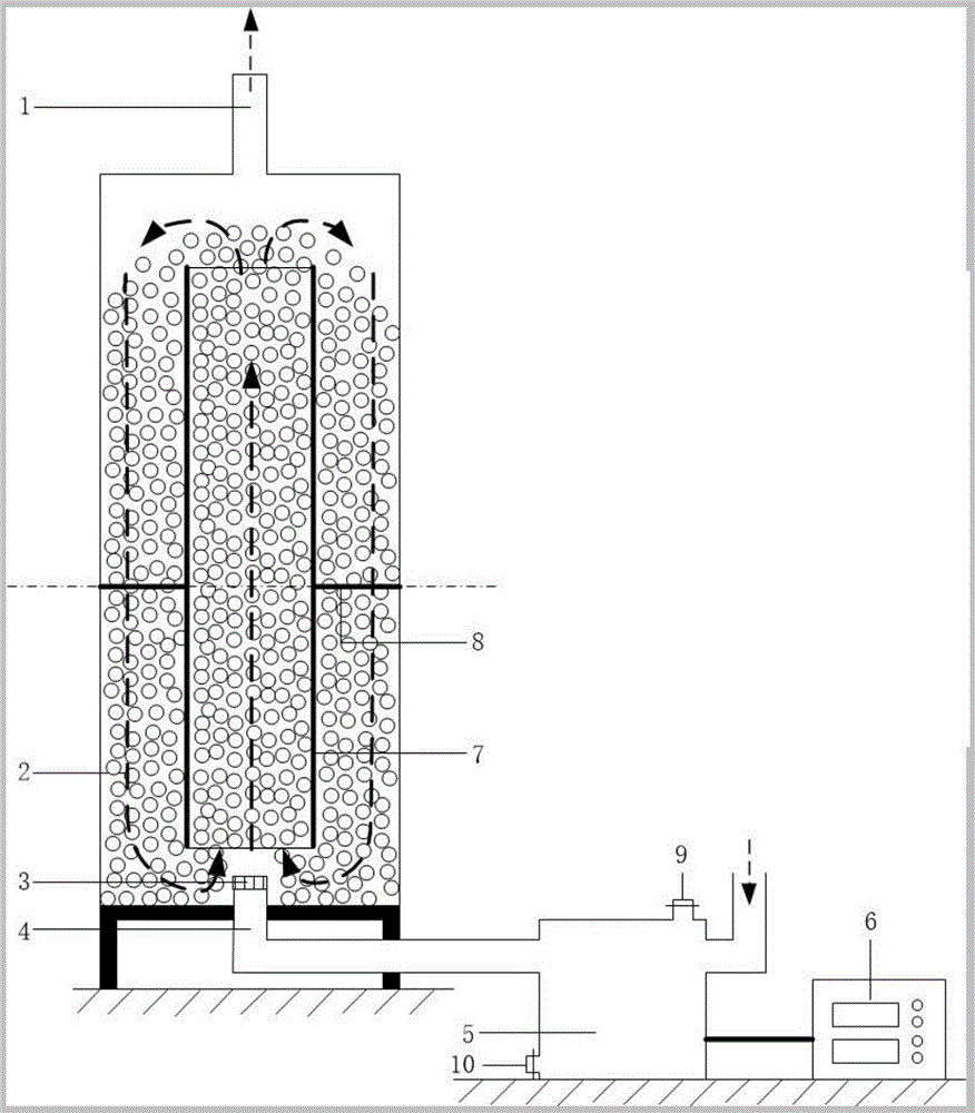
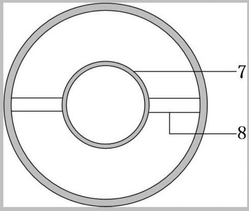
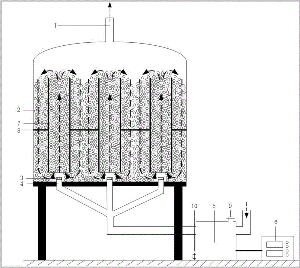
[0020] Such as figure 1 with figure 2 As shown, the present invention is a kind of internal circulating biological fluidized bed system for VOCs and malodorous gas treatment, the biological fluidized bed reactor adopts inner and outer sleeve structure, wherein, the inner layer sleeve 7 is used to form the fluidized packing The upflow zone, the outer layer of the sleeve is used as the downflow zone of the fluidized packing, the packing layer 2 in the biological fluidized bed reactor is polymer light packing, the air inlet 4 of the biological fluidized bed reactor is located at the bottom, and The humidification unit 5 is connected, and the air outlet 1 is located at the top, corresponding to the air inlet 4 .

[0021] Among them, the top of the inner sleeve of the biological fluidized bed reactor should have a height difference of more than 50...


PUM


Abstract

The invention discloses an internal-circulation biological fluidized bed system used for VOCs and malodorous gas treatments. The internal-circulation biological fluidized bed system used for the VOCs and malodorous gas treatments comprises a biological fluidized bed reactor which adopts a structure comprising an inner sleeve and an outer sleeve; the inner sleeve is used for forming an up-flow area of fluidized fillers, and the outer sleeve is used as a down-flow area of fluidized fillers, and the fillers are high-molecular light fillers; the air inlet of the biological fluidized bed reactor is located at the bottom, and is connected with a humidifying unit; the fillers in the reactor are in fluidized state; microorganisms attach on the surfaces of the fillers, so that the VOCs and the malodorous gas are removed by mass transfer and degradation processes when the VOCs and the malodorous gas pass through the reactor; and moisture and nutrients are uniformly transported into the gas by the humidifying unit. The fillers have the characteristics of light weight and easy fluidization property; the internal-circulation sleeve reactor structure is capable of ensuring fluidization of the fillers at a relatively low gas velocity; and the pressure drop of the reactor is relatively low. The internal-circulation biological fluidized bed system used for VOCs and malodorous gas treatment overcomes disadvantages of traditional biological waste-gas purification devices, namely low mass transfer efficiency and uneven microbial distribution, and can be used for purifying the VOCs and the malodorous gas in the fields of industry, municipal administration, agriculture and the like.

Description

technical field [0001] The invention belongs to the technical field of treatment of VOCs and malodorous waste gas, in particular to an internal circulation biological fluidized bed system for VOCs and malodorous gas treatment. Background technique [0002] Air pollution is one of the most prominent environmental problems at present. Especially in recent years, a large amount of volatile organic compounds (Volatile Organic Compounds, VOCs) and malodorous exhaust gas have caused regional atmospheric environmental problems such as urban haze and photochemical smog, seriously disturbing the daily life of residents, and threatening human health and ecological security. The "Thirteenth Five-Year Plan" includes VOCs in the total control index, and by 2020, the emissions will drop to more than 10%. In 2016, Shanghai, Beijing, Guangdong and other provinces and cities have started to collect VOCs emission fees. Therefore, research on effective treatment technologies for industrial V...

Claims


Application Information

Patent Timeline
Patent Type & Authority Applications(China)
IPC IPC(8): B01D53/84B01D53/72
CPCB01D53/72B01D53/84Y02A50/20
Inventor 席劲瑛陆李超郑倩
Owner TSINGHUA UNIV
Why Eureka
Try Eureka