Method and equipment for producing coal gas through biomass pressurized gasification

A technology of pressurized gasification and biomass, applied in gasification process, manufacture of combustible gas, petroleum industry, etc., can solve problems such as unresolved equipment blockage and corrosion, no adjustment of syngas ratio, single ratio of syngas, etc., to achieve Less pollution, less treatment capacity, lower operating costs

Active Publication Date: 2017-05-10
SEDIN ENG
View PDF7 Cites 4 Cited by
  • Summary
  • Abstract
  • Description
  • Claims
  • Application Information

AI Technical Summary

Problems solved by technology

Fluidized bed gasifiers can be divided into bubbling fluidized bed gasifiers, circulating fluidized bed gasifiers and double fluidized bed gasifiers, which have the characteristics of uniform heating and low tar content. pressure or low pressure, the gasification pressure will not exceed 1.0MPa, the processing capacity is small, the tar generated during gasification will cause blockage and corrosion to subsequent equipment, and the synthesis gas produced by gasification H 2 / CO ratio is single, and there are many problems in the gasification wastewater containing dust and tar
[0004] Chinese patent, patent number: 201210493250.4 discloses a method and device for preparing synthesis gas by pressurized gasification of a biomass fixed bed. The problem of clogging and corrosion of equipment, and the H of syngas 2 The / CO ratio also has no adjustment function, and even more dusty and tar-containing gasification wastewater is produced during the gasification process
[0005] After searching, no method has been found to produce coal gas by pressurized gasification using biomass as raw material through fixed bed at a pressure higher than 1.0 MPa, especially the technology of producing gas without oil, organic sulfur and hydrocarbons by pressurized gasification of fixed bed

Method used


Image

  • Method and equipment for producing coal gas through biomass pressurized gasification
  • Method and equipment for producing coal gas through biomass pressurized gasification

Examples


Embodiment 1

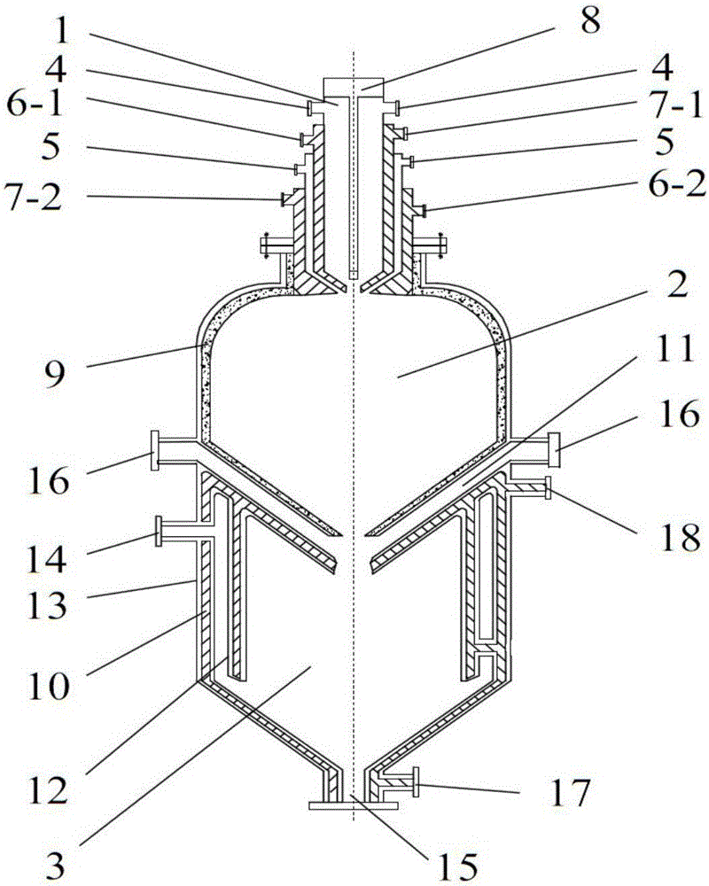
[0040] Integrated oil and gas cracking purifier, which includes burner 1, cracker 2 and purifier 3. Burner 1, cracker 2 and purifier 3 are coupled into one body. The top of cracker 2 is connected to burner 1, cracker 2 and The purifier 3 is connected as a whole through the shell 13, the upper part is the cracker 2, and the lower part is the purifier 3.

[0041] The burner 1 is provided with a gas inlet 4, an oxygen inlet 5, a cooling water inlet, a cooling water outlet, and an ignition inspection device 8. From the inside to the outside, from top to bottom, there are a gas channel, a first cooling water channel, and an oxygen channel. The second cooling water channel, the gas channel has a gas inlet 4, the first cooling water channel has a first cooling water inlet 6-1, the first cooling water outlet 7-1, the oxygen channel has an oxygen inlet 5, and the second cooling water channel has The second cooling water inlet 6-2, the second cooling water outlet 7-2, there is an ignition ...

Embodiment 2

[0049] The porous medium loaded into the purifier 3 is activated carbon, and the filling amount is 11 / 18 of the purifier volume.

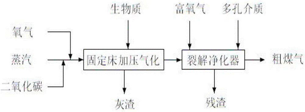
[0050] The biomass is prepared into poplar wood with a particle size of 12mm-60mm and fed into the gasification furnace through a silo. The ratio of steam, oxygen and carbon dioxide is 4.5kg:1Nm 3 :3.7Nm 3 , The gasification pressure is 3.0MPa, the temperature is 850 degrees, and the gas is gasified by the gasifier. The generated coal gas and oxygen are mixed through the burner at a volume ratio of 1:1.0-5.0 and then enters the cracker at a speed of 67m / s , It burns and cracks at a temperature higher than 1305 degrees to produce small molecular substances. The small molecules generated by the cracking enter the purifier, and the dust is removed when the porous medium is filled, so that the dust content in the crude gas of the purifier is less than 5mg. The heat generated is recovered through the double jacket to produce saturated steam with a pressure ...

Embodiment 3

[0052] The porous medium loaded into the purifier 3 is coke, and the filling amount is 1 / 2 of the volume of the purifier.

[0053] The biomass is prepared into poplar wood with a particle size of 15-70mm and fed into the gasifier through a silo, with the ratio of steam, oxygen and carbon dioxide being 4kg:1Nm 3 :3.8Nm 3 The ratio of steam to oxygen is 4.0kg / Nm 3 , The gasification pressure is 2.45MPa, the temperature is 860 degrees, and the gasification is through the gasifier. The generated coal gas and oxygen are mixed through the burner at a volume ratio of 1:9.15 and then enters the cracker at a speed of 65m / s. It burns and cracks at 1356 degrees to produce small molecules. The small molecules generated by the cracking enter the purifier, and the dust is removed when the porous medium is filled, so that the dust content in the crude gas of the purifier is below 3mg. The heat generated is recovered through the double jacket to produce saturated steam with a pressure of 2.2MPa. ...


PUM

PropertyMeasurementUnit
particle diameteraaaaaaaaaa
particle sizeaaaaaaaaaa
particle diameteraaaaaaaaaa

Abstract

The invention provides a method for producing coal gas through biomass pressurized gasification. The method includes the steps that biomass is added into a gasification furnace, a gasifying agent enters the gasification furnace from the gasification furnace bottom for gasification, dust-containing and oil-containing coal gas generated through the gasification is sent into an integrated oil and gas cracking purifier for cracking and purification, is subjected to high-temperature cracking in a cracker combustion chamber and then enters a purifier, circulating water is pumped in a double-layer water jacket of the purifier, the purifier is filled with porous media which are used for recycling heat in the cracker and adsorbing dust in the coal gas, the coal gas obtained after heat recycling is led out of a coal gas outlet through a coal gas channel, and at the same time, saturated steam is produced. The method has the advantages that synthesis gas which is free of tar and adjustable in H2/CO specific value is continuously and stably produced, and coal gas water has little pollution.

Description

Technical field [0001] The invention belongs to a method for producing coal gas, and particularly relates to a method and equipment for producing coal gas by pressurized gasification of biomass. Background technique [0002] Energy is the foundation for the survival and development of modern society. The supply capacity of energy is closely related to the sustainable development of the national economy and is one of the foundations of national strategic security guarantee. At present, my country's main energy sources come from fossil energy such as coal, oil, and natural gas. As a one-time energy source, apart from limited storage, fossil energy will inevitably cause air pollution, atmospheric warming, sea level rise, acid rain and other environmental problems when used. From a long-term perspective, one or more renewable energy sources must be sought as a supplement for diversified development. Biomass energy is a low-sulfur fuel that is renewable and does not increase greenhou...

Claims


Application Information

Patent Timeline
Patent Type & Authority Applications(China)
IPC IPC(8): C10J3/20C10J3/76C10J3/80C10J3/84
CPCC10J3/20C10J3/76C10J3/80C10J3/84C10J2300/0916C10J2300/1207C10J2300/1687
Inventor 左永飞崔晓曦闫少伟韩涛宋乐
Owner SEDIN ENG
Why Eureka
Try Eureka