Ultra-high-speed electro-optical signal generator based on graphene microfiber with three-dimensional grating structure

A technology of signal generator and gate structure, which is applied in the directions of instruments, optics, nonlinear optics, etc., can solve the problems of reducing long-term stability, environmental temperature distribution and vibration sensitivity, and the disadvantages of large-scale device integration, and achieve low coupling loss , easy to produce finely, low transmission loss effect

Active Publication Date: 2019-05-07
BEIJING JIAOTONG UNIV
View PDF3 Cites 0 Cited by
  • Summary
  • Abstract
  • Description
  • Claims
  • Application Information

AI Technical Summary

Problems solved by technology

At the same time, large-scale devices are sensitive to ambient temperature distribution and vibration, which reduces their long-term stability
In addition, large-size devices have disadvantages in terms of integration

Method used


Image

  • Ultra-high-speed electro-optical signal generator based on graphene microfiber with three-dimensional grating structure
  • Ultra-high-speed electro-optical signal generator based on graphene microfiber with three-dimensional grating structure
  • Ultra-high-speed electro-optical signal generator based on graphene microfiber with three-dimensional grating structure

Examples


Embodiment 1

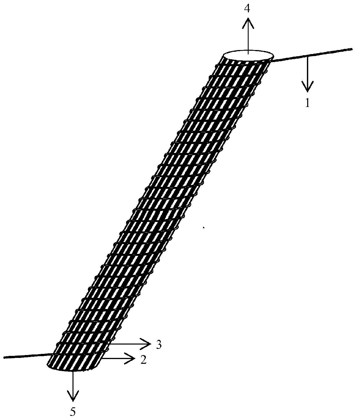
[0049] like figure 1 As shown, the ultra-high-speed electro-optic signal generator based on the three-dimensional grid structure graphene micro-fiber includes a micro-fiber 1, a rod-shaped substrate 2, a graphene grid structure layer 3, a positive electrode 4, and a negative electrode 5.

[0050] The specific combination method is: the graphene grid structure layer 3 surrounds the side surface of the rod-shaped substrate 2, the fine optical fiber 1 is wound on the surface of the rod-shaped structure covered with the graphene layer 3, and the two ends of the rod-shaped structure are respectively positive electrode 4 and negative electrode 5 and graphite The graphene grid structure layer 3 is connected to provide a voltage to change the absorption effect of the graphene grid structure layer 3 on the carrier.

[0051] The thickness of the graphene grid structure layer 3 is 0.335 nm, and the period length of the graphene grid structure layer 3 is 1.2 mm.

[0052] The rod-shaped b...

Embodiment 2

[0056] like figure 1 As shown, the ultra-high-speed electro-optic signal generator based on the three-dimensional grid structure graphene micro-fiber includes a micro-fiber 1, a rod-shaped substrate 2, a graphene grid structure layer 3, a positive electrode 4, and a negative electrode 5.

[0057] The specific combination method is: the graphene grid structure layer 3 surrounds the side surface of the rod-shaped substrate 2, the fine optical fiber 1 is wound on the surface of the rod-shaped structure covered with the graphene layer 3, and the two ends of the rod-shaped structure are respectively positive electrode 4 and negative electrode 5 and graphite The graphene grid structure layer 3 is connected to provide a voltage to change the absorption effect of the graphene grid structure layer 3 on the carrier.

[0058] The thickness of the graphene grid structure layer 3 is 0.335 nm, and the period length of the graphene grid structure layer 3 is 1.2 mm.

[0059] The rod-shaped b...


PUM

PropertyMeasurementUnit
diameteraaaaaaaaaa
thicknessaaaaaaaaaa
lengthaaaaaaaaaa

Abstract

The invention relates to a superspeed electro-optical signal generator based on three-dimensional grating structure graphene micro optical fiber. The signal generator comprises the micro optical fiber, a rodlike substrate and a graphene grating structural layer; the micro optical fiber is wound around the surface of the rodlike structure, the two end faces of the rodlike structure are a positive electrode and a negative electrode respectively, and the positive electrode and the negative electrode are connected with the graphene grating structural layer. The superspeed electro-optical signal generator is not sensitive to the operating environment; a spatial modulation mode is adopted, and superspeed optical signals are generated at a low electric signal conversion speed; graphene is adopted as a modulation material, and the advantages of being super-short in response time, super-wide in wavelength modulation range, low in power consumption and high in area efficiency are achieved; the micro optical fiber is adopted as a basic waveguide, the superspeed electro-optical signal generator is compatible with an existing optical fiber communication system, and input / output coupling losses are quite low; carrier waves are transmitted in the micro optical fiber through a basic mode, and transmission losses are quite low; the superspeed electro-optical signal generator is quite small in size and has the great advantage in the aspect of integration.

Description

technical field [0001] The invention belongs to the field of optical fiber devices for communication, in particular to an ultra-high-speed electro-optical signal generator based on a three-dimensional grid structure graphene micro-fiber. Background technique [0002] Optical Time Division Multiplexing (OTDM) adopts delay technology to delay and multiplex low-speed optical signals to form ultra-high-speed optical signals, which can realize ultra-high-speed communication in a single channel and is the backbone of modern communication The main technology of the main body of the network. [0003] Existing methods for generating ultra-high-speed optical signals rely on ultra-short pulse light sources, and the width and repetition rate of optical pulses determine the maximum multiplexing rate of the system. Mode-locked fiber lasers have poor stability when harmonic mode-locking is used, and long-term stable operation of mode-locked fiber lasers can be achieved when closed-loop er...

Claims


Application Information

Patent Timeline
Patent Type & Authority Patents(China)
IPC IPC(8): G02F1/035
CPCG02F1/035
Inventor 白冰裴丽
Owner BEIJING JIAOTONG UNIV
Why Eureka
Try Eureka