A kind of perc solar cell structure and preparation technology thereof

A solar cell and preparation technology, applied in the direction of sustainable manufacturing/processing, circuits, electrical components, etc., can solve the problems of LID light-induced attenuation increase, pollution, hidden cracks, etc., to increase process complexity, enrich hydrogen sources, The effect of preventing leakage

Active Publication Date: 2019-01-08
HENGDIAN GRP DMEGC MAGNETICS CO LTD
View PDF4 Cites 2 Cited by
  • Summary
  • Abstract
  • Description
  • Claims
  • Application Information

AI Technical Summary

Problems solved by technology

In the promotion of mass production of PERC cells, in addition to the need to solve quality problems including pollution and cracks, the other two key issues that need to be overcome are the low FF (fill factor) due to the local contact on the back and the quality of the passivation on the back. Increased LID (Light Induced Decay) due to lift

Method used


Image

  • A kind of perc solar cell structure and preparation technology thereof
  • A kind of perc solar cell structure and preparation technology thereof

Examples


Embodiment 1

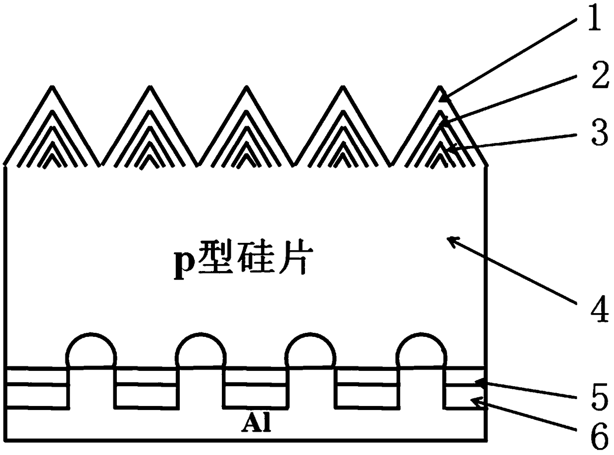
[0047] 1. Silicon wafers in alkaline (NaOH or KOH) or acidic solution (HF+HNO 3 ) after velvet making, wash, dry, and the velvet surface size is within 5um;

[0048] 2. Diffusion of high-temperature phosphorus is carried out in the diffusion furnace, the diffusion resistance is 80Ω / □, and the surface concentration is 6*10 20 atom / cm 3 , the junction depth is 300nm, after forming the pn junction, perform wet etching to remove the back junction and PSG;

[0049] 3. Oxidation is carried out in a high-temperature furnace at a temperature of 750°C and an oxidation time of 15 minutes. After oxidation, the surface concentration is 1.5*10 20 atom / cm 3 , the junction depth is 400nm; the temperature inside the tube is 750°C, and POCl 3 , the oxide layer is doped with impurities for 300s. After doping, the surface concentration is 5*10 20 atom / cm 3 ;

[0050] 4. Deposit the anti-reflection layer on the front side, using PECVD (introducing SiH 4 , NH 3 and N 2 O) depositing a Si...

Embodiment 2

[0057] In Example 1, in step 2, the diffusion resistance is 100Ω / □, and the surface concentration is 3*10 20 atom / cm 3 , the junction depth is 200nm, after the pn junction is formed, wet etching is performed to remove the back junction and PSG; the third step is to oxidize in a high-temperature furnace at a temperature of 750°C, and the oxidation time is 15min. After oxidation, the surface concentration is 9*10 19 atom / cm 3 , the junction depth is 300nm; the temperature inside the tube rises to 800°C, and POCl 3 , the oxide layer is doped with impurities for 300s. After doping, the surface concentration is 5*10 20 atom / cm 3 ; Other processes are the same as in Example 1.

Embodiment 3

[0059] In embodiment 1, in the 4th step, adopt PECVD (feed into SiH 4 , NH 3 and N 2 O) Deposit SiNx / SiOxNy / SiOx laminated structure on the emission area, SiNx refractive index is 2.2, film thickness is 5nm, SiOxNy refractive index is 1.9, film thickness is 30nm, SiOx refractive index is 1.6, film thickness is 40nm; Other Process is identical with embodiment 1.


PUM


Abstract

The invention discloses a PERC solar cell structure and a preparation process thereof. The PERC solar cell structure comprises a cell piece body. A SiO2 layer, an anti-reflection layer and an AlOx layer are successively deposited / grown on the front surface of the cell piece body. An AlOx layer and a SiNx layer are successively deposited on the back surface of the cell piece body. On the basis of a conventional PERC cell preparation process, a surface oxidation doping process is used. In addition, the PERC battery process is adjusted. A unique surface passivation layer deposition process is also used. The beneficial effect of the preparation process is that effective doping in an oxidation process improves the surface impurity concentration of the cell, improves the FF of the cell, compensate the deterioration of the FF due to the local contact on the back surface; and the adjustment of the PERC cell process solves edge electric leakage due to doping process so as to simply the process, thereby improving the conversion efficiency of the cell and providing a better hydrogenation effect for the subsequent photonic recovery process of the PERC battery so as to achieve anti-LID.

Description

technical field [0001] The invention relates to the technical field related to the manufacture of crystalline silicon solar cells, in particular to a structure of a PERC solar cell and a preparation process thereof. Background technique [0002] PERC cells use back passivation technology to effectively reduce the surface recombination rate and achieve the purpose of improving conversion efficiency. With the need to reduce the cost of photovoltaic power generation and the market's increasingly strong demand for high-efficiency components, the wave of mass production of PERC cells has officially arrived. In the promotion of mass production of PERC cells, in addition to the need to solve quality problems such as pollution and cracks, the other two key issues that need to be overcome are the low FF (fill factor) due to the local contact on the back and the quality of the passivation on the back. Increased LID (Light Induced Decay) due to lift. [0003] Judging from the current...

Claims


Application Information

Patent Timeline
Patent Type & Authority Patents(China)
IPC IPC(8): H01L31/0216H01L31/042H01L31/18
CPCH01L31/02167H01L31/02168H01L31/042H01L31/1876Y02E10/50Y02P70/50
Inventor 陈健生董方
Owner HENGDIAN GRP DMEGC MAGNETICS CO LTD
Why Eureka
Try Eureka