
A Method of Fabricating Spherical Concave Mirrors on Optical Waveguides Based on Laser Ring Etching

A spherical concave, laser etching technology, applied in the direction of light guide, optics, optical components, etc., can solve the problems of difficult to control droplet shape, high material requirements, complex process, etc., to reduce the possibility of additional drawbacks, improve vertical coupling Efficiency and simple production process

Active Publication Date: 2019-08-06
SHANGHAI UNIV
View PDF10 Cites 0 Cited by
  • Summary
  • Abstract
  • Description
  • Claims
  • Application Information

AI Technical Summary

Problems solved by technology

The patent (publication number: CN 1272182A) uses a chemical etching method to prepare a concave mirror, but this preparation method has problems such as low precision, complicated process, and convergence effect in only one direction; the patent (publication number: CN 103395739A) proposes a The method of making concave mirrors using the non-aggression of water molecules has high requirements on materials, and the droplet shape is difficult to control, so there are disadvantages of complicated process and low precision; "Design and fabrication of embedded micro-mirror inserts for out-of -plane coupling in PCB level optical interconnections” proposes deep proton writing (DPW) technology to process concave mirrors on optical waveguides, but it still has the disadvantages of complex process and difficult mass production
The method for preparing the above concave mirror has many problems in terms of materials, preparation technology, processing accuracy, etc., and it is difficult to meet the requirements of large-scale industrial production of optical backplanes.

Method used


Image

  • A Method of Fabricating Spherical Concave Mirrors on Optical Waveguides Based on Laser Ring Etching
  • A Method of Fabricating Spherical Concave Mirrors on Optical Waveguides Based on Laser Ring Etching
  • A Method of Fabricating Spherical Concave Mirrors on Optical Waveguides Based on Laser Ring Etching

Examples


Embodiment 1

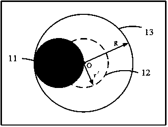
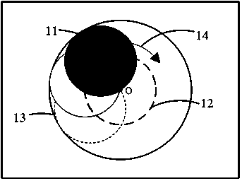
[0033] This embodiment specifically provides a processing flow for processing a spherical reflective concave surface on an optical waveguide based on an ArF excimer laser produced by OPTEC. The laser wavelength is 193 nm, and processing parameters such as laser power, moving step length, and mask pattern are optional. This embodiment uses a circular mask 11 ( Figure 2A Shown) for laser etching, the preparation process is as follows.

[0034] First, determine the processing area on the cladding surface of the optical waveguide. The diameter of the spherical concave surface to be processed must be larger than the cross-sectional width of the optical waveguide core layer so as to be able to receive all the transmitted light from the core layer. The spherical center O is symmetrically longitudinally cut on the optical waveguide core layer. On a flat surface, to ensure that the reflected beam from the spherical reflective concave surface converges directly above the concave surface to...

Embodiment 2

[0042] This embodiment uses an elliptical mask pattern 18 (such as Figure 3A Shown) The spherical reflective concave surface is processed on the optical waveguide.

[0043] The processing idea and etching process of this embodiment are basically the same as those of the first embodiment, but the shape of the processed spherical reflective concave surface is different. Let the elliptic equation be The ellipse mask is rotated and etched along a circular path at a certain angular velocity, the center of the ellipse always moves along the circular etching path 153, and one end of the minor axis of the ellipse always coincides with the center O of the reflective spherical concave surface. Take O as the center and radius as r i The etching depth of each point of the circle is the same. Select the two points A and B of the etched area as the analysis. For point A, take the center O and the radius r A The circle made passes through point A, the total depth of point A is the laser arc l...

Embodiment 3

[0047] In this embodiment, a free-curve surface mask pattern is used to etch the spherical reflective concave surface on the optical waveguide, and a strict spherical reflective concave surface can be obtained. The etching process is similar to the first embodiment. The free-form surface mask 19 pattern is obtained by inversely deducing the strict spherical reflection concave function to be obtained, such as Figure 4A Shown.

[0048] Can be combined Figure 4A Jinhe Figure 4B Determine the function expression of the free curve surface. Since the processed transverse cross-sectional figure is a semicircle with a radius of R, mark the etching depth of point A as H A , The length of the laser arc line that needs to sweep point A is l A , Under the determination of the laser power P, the etching depth of a fixed-point etching is h 0 , The distance from each point in the mask pattern to point O on the spherical reflective concave surface is r. The function expression of free curve s...


PUM


Abstract

The invention discloses a method for preparing a spherical concave mirror on an optical waveguide based on laser annular etching. According to the method, the coupling loss caused by unmatched optical waveguide-optical fiber vertical coupling factor numerical apertures is reduced. The method comprises the following machining flows: determining a machining region on the optical waveguide, and determining a radius r'=R / 2 of a laser round etching route according to the radius R of a to-be-machined reflecting spherical concave surface, wherein the round center of the reflecting spherical concave surface and the round center of the round etching route coincide; selecting laser etching mask figures which can be rounds, ovals, free curvilinear figures and the like; rotationally etching a mask along the round etching route, wherein the round center of the mask always moves along the round etching route, one point of periphery of the mask always coincides with the round center of the reflecting spherical concave surface, and the points of peripheries formed by virtue of the radiuses ri have different etching depths; carrying out rotary laser etching for one cycle, so as to form a sphere-similar reflecting concave surface; and processing the obtained double-side spherical reflecting concave surface, so as to obtain a single-side spherical reflecting concave surface.

Description

Technical field [0001] The invention relates to the field of micro-processing and manufacturing, and proposes a method for preparing a spherical concave mirror on an optical waveguide based on laser ring etching. Background technique [0002] In recent years, with the continuous increase in data processing speed requirements in the fields of broadband communications, supercomputers and big data centers, the research on high-speed bandwidth (≥50Gbps) related technologies has been promoted. The optical interconnection backplane technology based on Printed Circuit Board (PCB) has the advantages of high bandwidth, low energy consumption, and low cost, and has become a research hotspot in the field of high-end equipment information interconnection technology in recent years. [0003] At present, optical waveguides based on polymers are the most common optical waveguides, and vertical coupling technology is one of the key technologies for optical interconnection applications. How to achi...

Claims


Application Information

Patent Timeline
Patent Type & Authority Patents(China)
IPC IPC(8): G02B6/122G02B6/136
CPCG02B6/122G02B6/136
Inventor 王廷云邓传鲁刘琳琳庞拂飞
Owner SHANGHAI UNIV
Features
  • Generate Ideas
  • Intellectual Property
  • Life Sciences
  • Materials
  • Tech Scout
  • Unparalleled Data Quality
  • Higher Quality Content
  • 60% Fewer Hallucinations
Learn More