
Terminal-equipped electrical wire

A wire and terminal technology, used in circuits, conductive materials, conductive materials, etc., can solve the problems of low work efficiency, high yield strength, and can not withstand, and achieve the effect of improving work efficiency, high yield strength, and not easy to enter water.

Inactive Publication Date: 2017-05-24
FURUKAWA ELECTRIC CO LTD +1
View PDF8 Cites 6 Cited by
  • Summary
  • Abstract
  • Description
  • Claims
  • Application Information

AI Technical Summary

Problems solved by technology

Aluminum has poor bending fatigue characteristics compared to copper currently used, so the use of aluminum is limited
The second problem is that due to the high yield strength, a lot of force is required to install the wiring harness, and the work efficiency is low
The third problem is that due to poor elongation, it cannot withstand the impact when installing the wiring harness or after mounting, resulting in disconnection and cracks.

Method used


Image

  • Terminal-equipped electrical wire
  • Terminal-equipped electrical wire
  • Terminal-equipped electrical wire

Examples


Embodiment 1

[0117] Make Mg, Si, Fe, and Al and selectively added Cu, Zr, Ti, and B the contents (mass %) shown in Table 1, using the Propez type continuous casting and rolling machine, the casting mold after water cooling Continuously cast and rolled to make approx. of bars. The casting cooling rate at this time is 1°C / sec to 20°C / sec. Next, the first wire drawing was performed so that the processing ratio shown in Table 2 could be obtained. Next, intermediate heat treatment is performed on the workpiece subjected to the first wire drawing, and then the second wire drawing is performed at the same processing rate as the first wire drawing until the wire diameter reaches Next, solution heat treatment (first heat treatment) was implemented under the conditions shown in Table 3. In addition, in the solution heat treatment, a batch type heat treatment was adopted, and a thermocouple was wound around the wire rod to measure the temperature of the wire rod. In the continuous energization ...

Embodiment 2

[0119] Except that Mg, Si, Fe and Al and selectively added Cu, Mn, Cr, Zr, Au, Ag, Hf, V, Ni, Sc, Co, Ti and B are formulated into the contents (mass %) shown in Table 4 Except, casting and rolling were carried out in the same manner as in Example 1, and approximately of bars. Next, the first wire drawing was performed so that the processing ratio shown in Table 5 could be obtained. Next, intermediate heat treatment is performed on the workpiece subjected to the first wire drawing, and then the second wire drawing is performed at the same processing rate as the first wire drawing until the wire diameter reaches Next, solution heat treatment (first heat treatment) was implemented under the conditions shown in Table 6. Then, after the solution heat treatment, aging heat treatment (second heat treatment) was performed under the conditions shown in Table 6 to manufacture aluminum alloy wires.

[0120] Each characteristic was measured by the method shown below about the produc...


PUM

PropertyMeasurementUnit
diameteraaaaaaaaaa
tensile strengthaaaaaaaaaa
diameteraaaaaaaaaa

Abstract

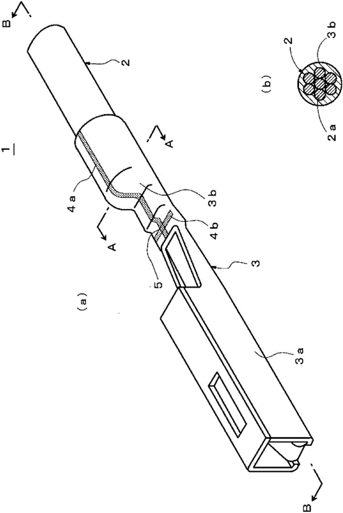
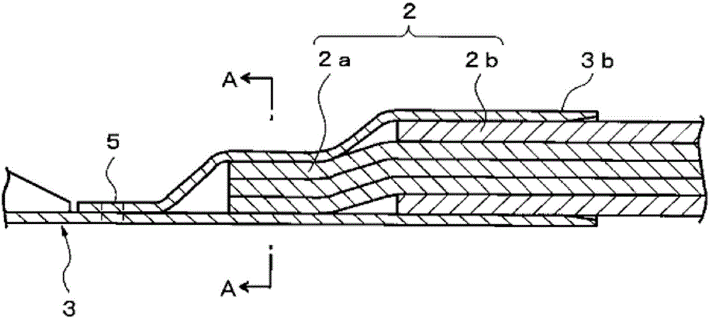
Provided is a terminal-equipped electrical wire that maintains the elongation properties and electrical conductivity of an aluminum alloy wire at levels equal to or greater than those of conventional products while achieving suitable yield strength and high bending fatigue resistance, that makes it difficult for moisture to enter the interior of a barrel section, and that makes it possible to configure a terminal so as to be compact in the lengthwise direction thereof. The terminal-equipped electrical wire (1) is provided with: an electrical wire (2) obtained by coating the outer circumference of an aluminum alloy wire (2a); and a crimp terminal (3) that is crimped to an end section of the electrical wire. The aluminum alloy wire (2a) comprises an Al-Mg-Si alloy. The crimp terminal (3) comprises a barrel section (3b) that is crimped together with the aluminum alloy wire (2a). The barrel section (3b) is configured to have a tubular shape of which one end is closed.

Description

technical field [0001] The present invention relates to an electric wire with a terminal using an aluminum alloy wire. Background technique [0002] Conventionally, wires made of copper or copper alloys (such as brass) mounted on wires containing copper or copper alloy conductors have been used as electrical wiring bodies for moving bodies such as automobiles, trains, and airplanes, or as electrical wiring bodies for industrial robots. Wires with terminals formed by terminals (connectors). [0003] In recent years, the high-performance and high-functionality of automobiles has been rapidly developed. Along with this, there is a tendency that the number of various vehicle-mounted electrical equipment and control equipment is increasing, and the number of electrical wiring bodies used in these equipment is increasing. also increase. In addition, on the other hand, for the sake of environmental protection, the fuel consumption of mobile bodies such as automobiles is to be imp...

Claims


Application Information

Patent Timeline
Patent Type & Authority Applications(China)
IPC IPC(8): H01B7/282C22C21/00H01B7/00H01R4/18H01R4/62C22F1/00C22F1/04
CPCC22C21/02C22C21/08C22F1/05C22C21/00C22F1/00C22F1/04H01B1/023H01B7/00H01B7/282H01R4/18H01R4/62H01B13/0003H01B13/0016H01B13/02H01B13/06
Inventor 吉田祥橘昭赖木原泰关谷茂树水户濑贤悟
Owner FURUKAWA ELECTRIC CO LTD
Learn More