Welding torch used for composite welding of laser beams and plasma arc

A hybrid welding and plasma arc technology, applied in laser welding equipment, welding equipment, metal processing equipment, etc., can solve the problems of laser beam welding application limitations, low energy conversion efficiency, unsuitable for laser welding, etc., and achieve high-efficiency plasma welding methods , Fast solidification of the weld bead, and the effect of eliminating laser welding defects

Inactive Publication Date: 2017-05-31
王长春
View PDF11 Cites 5 Cited by
  • Summary
  • Abstract
  • Description
  • Claims
  • Application Information

AI Technical Summary

Problems solved by technology

[0010] (1) A very precise position of the weldment is required (within the focus range of the laser beam), and the weldment needs to use a relatively complex fixture to ensure that the laser beam hot spot is aligned with the final position of the weldment; for thickness greater than 19mm The workpiece is not suitable for laser welding on the production line
[0011] (2) For materials with high reflectivity and high thermal conductivity such as aluminum, copper and their alloys, the application of laser beam welding is limited
[0012] (3) The energy conversion efficiency is usually lower than 10%; the weld bead solidifies quickly, which may cause pores and embrittlement
[0013] (4) Equipment is expensive
Normally, the welding torch can only complete one welding operation, which makes the welding operation complicated, and the user needs to purchase multiple welding torches and also spend more time to replace the welding torch, which affects the welding efficiency

Method used


Image

  • Welding torch used for composite welding of laser beams and plasma arc
  • Welding torch used for composite welding of laser beams and plasma arc
  • Welding torch used for composite welding of laser beams and plasma arc

Examples


Embodiment 1

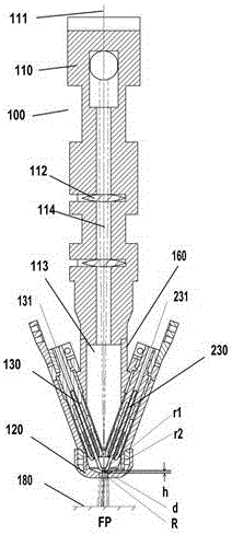
[0074] The torch 100 of the present invention includes a torch body 110 having a central axis 111 and a cavity 113 . On one end of the torch body 110 there is an optical system including a lens 112 . The lens 112 is used to focus the incident laser beam 114 such that the beam 114 is collinear with the central axis 111 of the torch body 110 and is focused to a focal point FP located outside the torch 100 .

[0075] exist figure 1 Among them, the welding torch main body 110 includes 2 (or 1, or 4 electrodes and arranged in pairs) electrodes 130 and 230, a compression nozzle 120, and a conical protective shield arranged concentrically with the compression nozzle 120 outside the compression nozzle Nozzles, both inside and outside of the compression nozzle 120 (between the compression nozzle 120 and the protection nozzle) pass through protective gas. The laser beam 114 has a certain radius r1 at the slit formed by the two electrodes, and has a certain radius r2 at the opening of ...

Embodiment 2

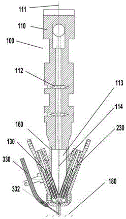
[0090] Such as figure 2 As shown, on the basis of Embodiment 1, the welding torch 100 also includes a wire feeding tube 330 for laser beam plasma wire filling welding, and the wire feeding tube 330 is arranged at an acute angle with the central axis 111 of the welding torch body 100, and Arranged on the opposite side of the welding torch 100 along the welding direction, the range of the acute angle between the wire feeding tube 330 and the central axis 111 of the welding torch body 100 is most preferably between 20° and 80°, and the best effect is to ensure that the welding wire and The plasma arc intersects the upper surface of the workpiece 180 without making the torch unwieldy in size. The longitudinal axis 332 of the wire liner 330 intersects the centerline 111 of the torch body at the upper surface of the workpiece 180 .

Embodiment 3

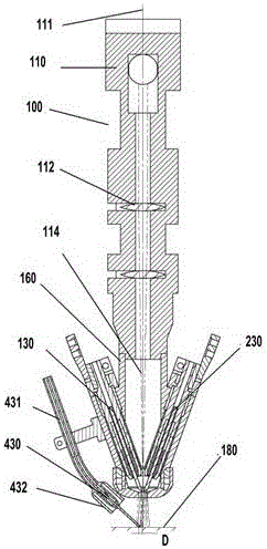
[0092] Such as image 3 As shown, on the basis of Embodiment 1, the welding torch 100 also includes a melting electrode contact tip 430 for laser beam plasma MIG welding, a wire feeding tube 431 and a protective gas jacket 432, and the conductive tip 430 is located in the protective gas jacket. 432 inside and concentric with 432; the contact tip 430 is arranged at an acute angle with the central axis 111 of the welding torch body 100, and the acute angle is in the range of 0 to 60 degrees, and is arranged on the opposite side of the welding torch 100 along the welding direction. The longitudinal axis 432 intersects the centerline 111 of the torch body 110 below the upper surface of the workpiece 180, and is at a distance D from the intersection point of the centerline 111 of the torch on the upper surface of the workpiece 180; D is defined as the melting electrode arc on the workpiece 180 The distance D between the arc impact point on the surface and the plasma arc impact poin...


PUM

PropertyMeasurementUnit
widthaaaaaaaaaa
energy conversion efficiencyaaaaaaaaaa

Abstract

A multifunctional laser beam and plasma arc composite welding torch is provided with a laser-penetrating cavity. A compression nozzle is arranged at the lower end of the welding torch cavity. A slit is formed through a plasma electrode on the compression nozzle of the welding torch. Parts of laser beams are incident on the slit edge of the electrode, and parts of the laser beams penetrate through the slit to focus on a workpiece. The electrode heated by the laser beams causes gas ionization to form a plasma arc between the electrode and the compression nozzle firstly. After compressed by the compression nozzle, the plasma arc is built between the nozzle and the workpiece. The laser beams penetrating through the nozzle focus and interact with the plasma arc to form plasma-laser discharging, accordingly the plasma arc is further contracted, and under the combined action with the laser beams, a welding point with the high energy density is formed on the workpiece. The multifunctional laser beam-plasma arc composite welding torch removes the defects of laser welding and plasma welding and has the composite heat source coupling efficiency higher than that of conventional laser beam-electric arc composite welding.

Description

technical field [0001] The invention relates to a welding torch device for welding and coating of metal materials, specifically, a welding torch for hybrid welding of laser and plasma arc, and the hybrid welding method of laser and plasma arc of the invention. Background technique [0002] Welding is a processing and manufacturing technology that is crucial in various metal manufacturing industries and cannot be completely replaced so far. Welding refers to the generation of high energy density on the workpiece to form a molten pool and move the molten pool. Therefore, if the energy coupling efficiency between the welding tool and the workpiece, that is, the energy density incident on the workpiece, can be improved, significant economic benefits can be obtained, depending on the materials and welding techniques used. [0003] One of them is plasma welding with high energy coupling density. Plasma welding refers to a process technology that uses compressed plasma arc as an e...

Claims


Application Information

Patent Timeline
Patent Type & Authority Applications(China)
IPC IPC(8): B23K26/348B23K26/70
CPCB23K26/348B23K26/702
Inventor 王长春陈卓勤
Owner 王长春
Why Eureka
Try Eureka