

Manufacturing method of direct-light-type LED backlight
A technology for an LED backlight source and a manufacturing method, which is applied to electrical components, electric solid-state devices, circuits, etc., can solve the problems of low light conversion efficiency, high production cost, and complicated manufacturing process of quantum dot light-emitting devices, and achieve high light conversion efficiency. , the effect of high excitation efficiency and low production cost
- Summary
- Abstract
- Description
- Claims
- Application Information
AI Technical Summary
Problems solved by technology
Method used
Image


Examples
Embodiment 1
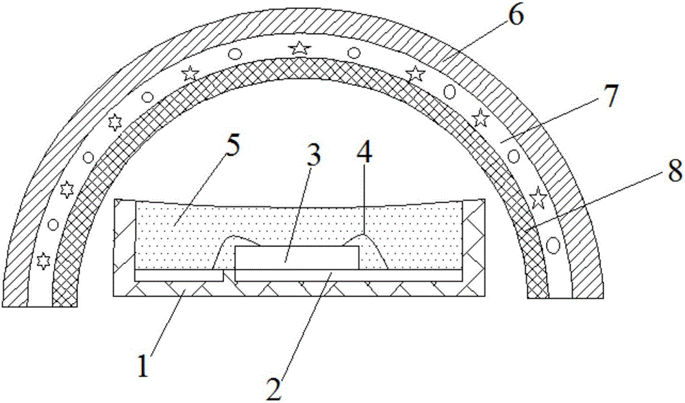
[0029] This embodiment provides a method for manufacturing a direct-lit LED backlight, the method comprising the following steps:
[0030] a. Weigh 0.02g of CdTe and ZnSe quantum dot phosphors with an emission wavelength of 620nm, of which 0.01g of CdTe quantum dot phosphors, and weigh 0.013g of PbZrO with an emission peak wavelength of 545nm 3 The green light quantum dot phosphor is uniformly mixed with the three quantum dot phosphors to obtain a mixed phosphor, and the quantum dot phosphor is in powder form;
[0031] b. Weigh 9.9g of epoxy photocurable glue and add it into the mixed fluorescent powder, then carry out vacuum stirring, and stir evenly to obtain quantum dot fluorescent glue;
[0032] c. Coating the quantum dot fluorescent glue on the inner surface of the LED lens. In this embodiment, the coating thickness of the quantum dot fluorescent glue is 5 μm, and the LED lens is placed in an ultraviolet curing furnace. Irradiate with 230nm ultraviolet light for 3s to cu...
Embodiment 2
[0037] This embodiment provides a method for manufacturing a direct-lit LED backlight, the method comprising the following steps:
[0038]a. Weigh 0.04g of red light BaTiO with a light emitting wavelength of 628nm 3 Quantum dot phosphor, and weigh 0.012g of AgInS with the peak wavelength of emitted light at 455nm 2 Blue light quantum dot phosphor powder and 0.028g GaS green light quantum dot phosphor powder with emission wavelength of 539nm, three kinds of quantum dot phosphor powders are mixed evenly to obtain mixed phosphor powder, and the quantum dot phosphor powder is solvent dispersed;
[0039] b. Weigh 0.08g of silicone-based light-curable glue and add it to the mixed fluorescent powder, then carry out vacuum stirring, and stir evenly to obtain quantum dot fluorescent glue;
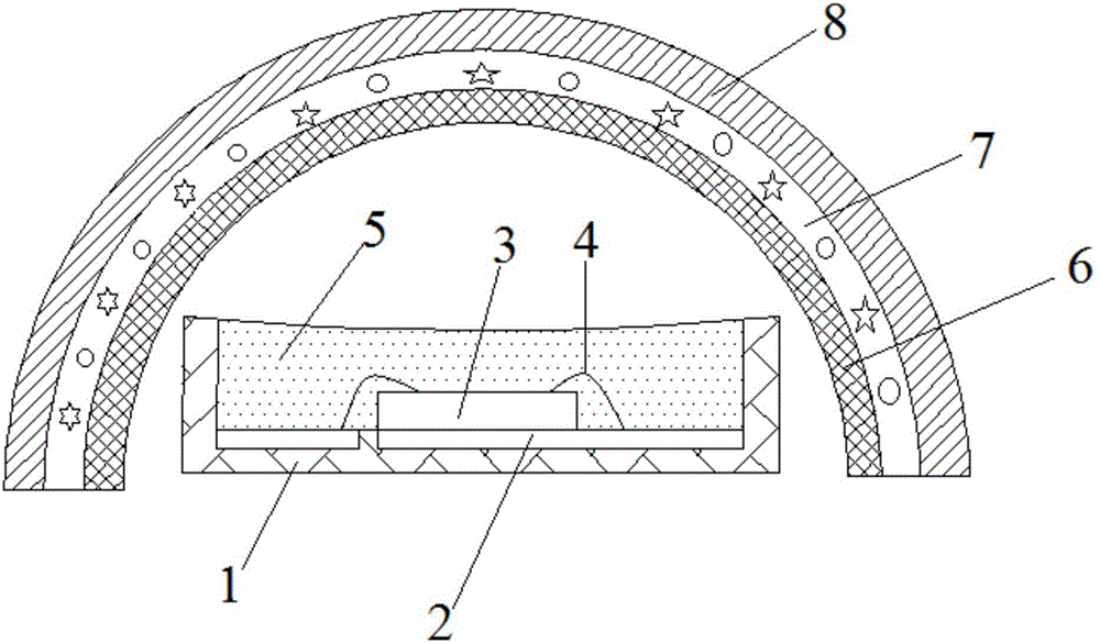
[0040] c. Coating the quantum dot fluorescent glue on the outer surface of the LED lens. In this embodiment, the coating thickness of the quantum dot fluorescent glue is 500 μm, and the LED lens is...
Embodiment 3
[0045] This embodiment provides a method for manufacturing a direct-lit LED backlight, the method comprising the following steps:
[0046] a. Weigh 0.54g of fluoride red phosphor powder with emission wavelength of 632nm, and weigh 0.012g of GaAs and GaN green light quantum dot phosphor powder with emission peak wavelength of 535nm, and mix the three phosphors evenly to obtain mixed fluorescence powder, the quantum dot fluorescent powder is powder;
[0047] b. Weigh 1.31g of polyurethane light-curable glue and add it into the mixed fluorescent powder, then carry out vacuum stirring, and stir evenly to obtain quantum dot fluorescent glue;
[0048] c. Coating the quantum dot fluorescent glue on the outer surface of the LED lens. In this embodiment, the coating thickness of the quantum dot fluorescent glue is 180 μm, and the LED lens is placed in an ultraviolet curing furnace. Irradiate with 365nm ultraviolet light for 50s to cure the quantum dot fluorescent glue;
[0049] d. Th...
PUM
| Property | Measurement | Unit |
|---|---|---|
| Wavelength | aaaaa | aaaaa |
| Thickness | aaaaa | aaaaa |
| Coating thickness | aaaaa | aaaaa |
Abstract
Description
Claims
Application Information