Method of extracting and separating catalytic cracking slurry oil

A catalytic cracking oil slurry and extraction technology, which is applied in the petroleum industry, refined hydrocarbon oil, and only multi-stage serial refining process treatment, etc., can solve the problems of insufficient separation, improve low utilization rate, enhance economic benefits, alleviate The effect of wasting resources

Active Publication Date: 2017-06-13
CHINA UNIV OF PETROLEUM (BEIJING)
View PDF5 Cites 5 Cited by
  • Summary
  • Abstract
  • Description
  • Claims
  • Application Information

AI Technical Summary

Problems solved by technology

Judging from the results of the examples of this method, the separation of this method is not thorough enough, and the colloid and asphaltene contents in the aromatic hydrocarbon components are both above 10%, which is not suitable for making high value-added needle coke

Method used


Image

  • Method of extracting and separating catalytic cracking slurry oil
  • Method of extracting and separating catalytic cracking slurry oil
  • Method of extracting and separating catalytic cracking slurry oil

Examples


Embodiment 1

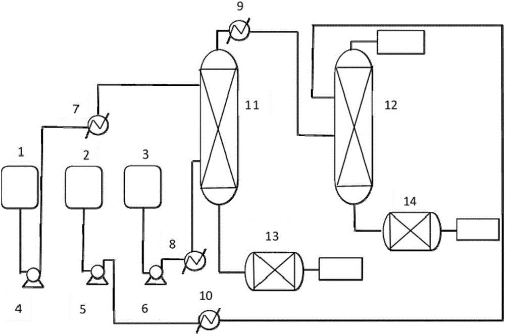
[0039] This embodiment provides a method for extracting and separating catalytic cracking oil slurry, which is carried out by using an extraction tower. The specific process is as follows figure 1 shown. The method includes the following steps:

[0040] Using dimethyl sulfoxide as the solvent 1, make it enter the upper part of the first-stage extraction tower 11, and the oil slurry 1 enters the lower part of the first-stage extraction tower 11, the solvent-oil mass ratio is 3:1, the temperature is 70°C, and the pressure It is 1MPa, and the two are countercurrently contacted in the tower, and the component discharged from the bottom of the first-stage extraction tower 11 is the colloidal component, and enters the solvent evaporator 13;

[0041] The extraction phase of the first-stage extraction tower 11 enters the bottom of the second-stage extraction tower 12 from the top of the tower, the solvent 2 is furfural, and enters the upper part of the second-stage extraction tower 1...

Embodiment 2

[0052] This embodiment provides a method for extracting and separating catalytic cracking oil slurry, which is carried out by using an extraction tower. The specific process is as follows figure 1 shown. The method includes the following steps:

[0053] Using dimethyl sulfoxide as the solvent 1, make it enter the upper part of the first-stage extraction tower 11, and the oil slurry 1 enters the lower part of the first-stage extraction tower 11, the solvent-oil mass ratio is 3:1, the temperature is 75°C, and the pressure It is 1.2MPa, and the two are countercurrently contacted in the tower, and the component discharged from the bottom of the first stage extraction tower 11 is the colloidal component, and enters the solvent evaporator 13;

[0054] The extraction phase of the first-stage extraction tower 11 enters the bottom of the second-stage extraction tower 12 from the top of the tower, the solvent 2 is furfural, and enters the upper part of the second-stage extraction tower...


PUM


Abstract

The invention provides a method of extracting and separating catalytic cracking slurry oil. The method comprises the step of adopting a polar non-proton solvent to conduct secondary extraction on the catalytic cracking slurry oil. According to the method of extracting and separating the catalytic cracking slurry oil, the catalytic cracking slurry oil is divided into a saturated hydrocarbon component, an aromatic hydrocarbon component and a colloid component through the secondary extraction, the current condition of low use ratio of the catalytic cracking slurry oil is improved, the catalytic cracking slurry oil is divided into multiple components selectively and is utilized hierarchically so that a subsequent processing scheme can be selected with pertinence, and the method is conducive to improvement of additional value of a product; besides, sulfur, nitrogen and heavy metal components can be removed in the aromatic hydrocarbon component to some extent, and catalyst poisoning, or coking requirements of a device and the like in the subsequent processing process are avoided.

Description

technical field [0001] The invention relates to a method for extracting and separating catalytic cracking oil slurry, which belongs to the technical field of petroleum processing. Background technique [0002] Catalytic cracking is the main means of lightening heavy oil. At present, most refineries in my country have catalytic cracking units, and their products cover gasoline, kerosene, diesel and liquefied petroleum gas. [0003] The catalytic cracking oil slurry contains 15-40% saturated hydrocarbons, 40-60% aromatic hydrocarbons, and the rest are colloids and asphaltenes. Aromatic components account for the majority, and most of them are short-chain condensed ring aromatic hydrocarbons, and aromatic components with aromatic carbon numbers of 2-4 account for more than 70%. These aromatic components exist in the catalytic cracking oil slurry, which are easy to polycondensate into charcoal, form equipment fouling, and affect product quality and distribution. In order to re...

Claims


Application Information

Patent Timeline
IPC IPC(8): C10G21/16C10G21/27C10G53/06
CPCC10G21/16C10G21/27C10G53/06
Inventor 刘艳升曹睿伍洛刘拥军
Owner CHINA UNIV OF PETROLEUM (BEIJING)
Why Eureka
Try Eureka