Device system and method for achieving carbon dioxide cyclic power generation through geothermal energy

A cycle power generation, carbon dioxide technology, applied in geothermal energy systems, geothermal energy power generation, mechanical equipment, etc., can solve the problems of large system investment, unsuitable cycle power generation technology and equipment, environmental hazards, etc., to achieve the effect of application safety

Active Publication Date: 2017-06-20
长沙紫宸科技开发有限公司
View PDF5 Cites 12 Cited by
  • Summary
  • Abstract
  • Description
  • Claims
  • Application Information

AI Technical Summary

Problems solved by technology

But there are the following main problems in this scheme: First, the liquefied CO 2 Pressed into the geothermal layer and then drawn out from another drilling pipeline, the investment is large and the energy consumption is large; second, the liquefaction of CO 2 Pressed into the geothermal layer, in addition to high risk, objectively uncontrollable, and prone to safety accidents, the pressed CO 2 It will also acidify the geology and displace a large amount of hydrocarbons such as methane into the atmospheric ecosystem, causing unpredictable environmental hazards
[0005] The supercritical carbon dioxide power generation system developed with the application of CCS technology has significant advantages over traditional thermal power generation systems in terms of system thermal efficiency, total weight, floor area, and pollutant emissions, but there are still many bottlenecks in application. First, the high-efficiency heat exchanger of the existing supercritical carbon dioxide power generation system is the basis for the engineering application of the supercritical power generation system. Most of the heat exchange of the road uses a printed circuit board heat exchanger (PCHE), which is suitable for high working temperature and high working pressure, and has good expansion ability, which can meet the requirements of isobaric heating of carbon dioxide with a heat exchanger. However, its mechanism is complex and the investment is large; secondly, the current supercritical carbon dioxide power generation system includes a heat source, a high-speed turbine, a high-speed generator, a high-speed compressor, a cooler, etc., and its cycle process is that supercritical carbon dioxide is boosted by a compressor—— Use a heat exchanger to heat the carbon dioxide working medium at equal pressure—the working medium enters the turbine to drive the turbine to do work to drive the motor to generate electricity—the working medium enters the cooler—then enters the compressor to form a closed cycle, and the system investment is large; third, the current ultra- The critical carbon dioxide Brayton cycle requires the compressor parameters to be close to the critical point to reduce the heat exchange end difference. The compression work of the compressor still accounts for more than 30% of the turbine output work during the compression process, and the actual compression work still accounts for 30% of the turbine output work. 40% to 50% of the output work, that is, the self-consumption energy of the compressor of the system is still relatively high; moreover, the high efficiency of the system cycle needs to be established when the carbon dioxide at the outlet of the condenser, that is, the suction inlet of the compressor (the starting point of the cycle) is still at 32 ℃, 7.4MPa at the critical point of the supercritical state, it is difficult to control the operation state of the supercritical carbon dioxide power generation system, and control research still needs to be carried out
Existing supercritical CO 2 Cyclical power generation technology and equipment are not very suitable for my country's national conditions

Method used


Image

  • Device system and method for achieving carbon dioxide cyclic power generation through geothermal energy
  • Device system and method for achieving carbon dioxide cyclic power generation through geothermal energy
  • Device system and method for achieving carbon dioxide cyclic power generation through geothermal energy

Examples


Embodiment 1

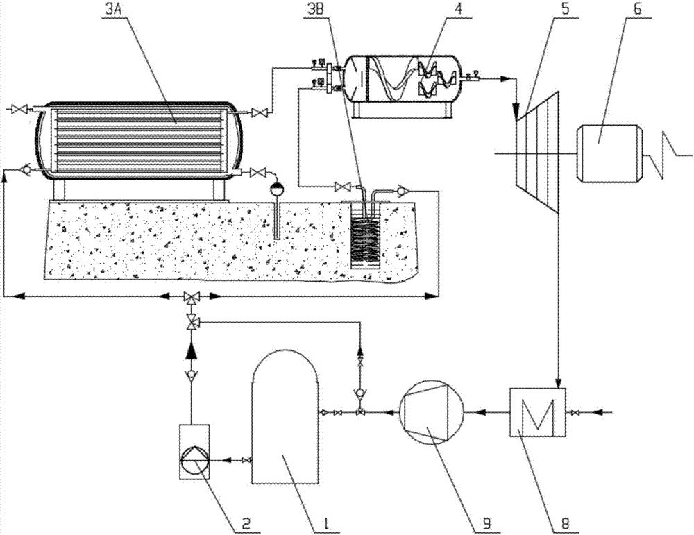
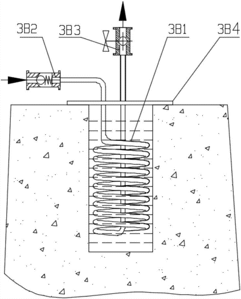
[0055] Such as Figure 1~4 As shown, the present invention provides an equipment system for utilizing geothermal energy to realize carbon dioxide cycle power generation, mainly including liquid CO 2 Storage tank 1, high pressure pump / compressor 2, geothermal energy CO 2 Energy storage device, steady flow regulator 4, turbine / piston expander 5, generator 6, cooler 8, compressor 9, the liquid CO 2 The outlet of the storage tank 1 is connected with the inlet of the high-pressure pump / compressor 2, and the outlet of the high-pressure pump / compressor 2 is connected with the geothermal energy CO 2 The inlet of the energy storage device is connected, and the geothermal energy CO 2 The outlet of the energy storage device is connected with the inlet of the steady flow regulator 4, and the outlet of the steady flow regulator 4 is connected with the inlet of the turbine / piston expander 5, and the turbine / piston expander 5 is connected with the generator 6-shaft connection, the outlet ...

Embodiment 2

[0062] Such as Figure 5 As shown, the difference between Embodiment 2 and Embodiment 1 is that it also includes a regenerator 7; the outlet of the turbine / piston expander 5 is connected to the low-pressure fluid inlet of the regenerator 7, and the low-pressure fluid inlet of the regenerator 7 The fluid outlet is connected to the inlet of the cooler 8, and the outlet of the cooler 8 is connected to the CO 2 The inlet of compressor 9 is connected, CO 2 The outlet of the compressor 9 is respectively connected to the high-pressure fluid inlet of the regenerator 7, the liquid CO 2 The inlet of storage tank 1 is connected. After the turbine or piston expander 5 works and releases energy, low-pressure CO is discharged. 2 Fluid, low pressure CO 2 The fluid recovers waste heat through the regenerator 7 and then cools through the cooler 8, CO 2 Compressor 9 compresses and sends into liquid CO 2 Tank 1 for circulation, or CO 2 The fluid compressed by the compressor 9 enters the g...

Embodiment 3

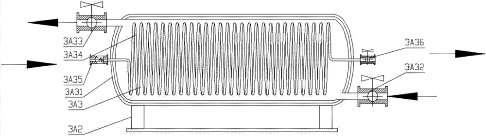
[0064] Such as Figure 6 As shown, the difference between embodiment 3 and embodiment 1 is that the geothermal energy CO 2 The energy storage device includes two desktop geothermal energy CO 2 The energy storage device 3A also includes a regenerator 7 in the equipment system; the outlet of the high-pressure pump / compressor 2 is respectively connected to two desktop geothermal energy CO 2 The inlet of the energy storage device 3A is connected, and the two desktop geothermal energy CO 2 The outlet of the energy storage device 3A is connected with the inlet of the steady flow regulator 4; the outlet of the turbine / piston expander 5 is connected with the low-pressure fluid inlet of the regenerator 7, and the low-pressure fluid outlet of the regenerator 7 is connected with the cooler The inlet of 8 is connected, and the outlet of cooler 8 is connected with CO 2 The inlet of compressor 9 is connected, CO 2 The outlet of the compressor 9 is respectively connected to the high-pres...


PUM


Abstract

The invention provides a device system and method for achieving carbon dioxide cyclic power generation through geothermal energy. The disclosed system comprises a liquid CO2 storage tank, a high-pressure pump / compressor, a geothermal energy CO2 energy storage device, a terrestrial heat production well, a steady flow adjuster, a turbine / piston expander, a power generator, a cooler and a CO2 compressor. The invention further discloses a method, in the method, low-pressure liquid CO2 fluid serves as a working medium, geothermal water and low-temperature CO2 fluid exchange heat with each other to form supercritical CO2 fluid different in temperature, pressure and energy density, then the equal-pressure supercritical CO2 fluid is achieved through adjustment of the steady flow adjuster, and then power generation is conducted. According to the device system and the method, heat energy in the geothermal water with the temperature ranging from 70 DEG C to 300 DEG C in the terrestrial heat production well is adopted for conducting energy storage on the liquid CO2, carbon dioxide cyclic power generation is achieved after tempering, the heat energy can be efficiently recycled, and high heat efficiency is improved; and energy in the terrestrial heat is effectively stored and utilized, and flexible adjustment and utilization of energy are achieved.

Description

technical field [0001] The invention relates to the technical field of low-carbon and energy utilization equipment, in particular to an equipment system and method for utilizing geothermal energy to realize carbon dioxide cycle power generation. Background technique [0002] Climate change has become one of the issues affecting human survival and development, and carbon dioxide emitted by industry is considered to be the main cause of climate warming. As the largest developing country in the world, our country uses coal as its primary energy and thermal power as its secondary energy as its energy structure. With the rapid growth of economic aggregate, the CO of primary energy and secondary energy 2 Emissions are characterized by rapid growth and large volumes. In response to climate change, the development of low-carbon energy, especially renewable energy and new energy, has become a consensus. The use of geothermal resources for power generation and supercritical carbon di...

Claims


Application Information

Patent Timeline
Patent Type & Authority Applications(China)
IPC IPC(8): F01K27/00F03G4/00
CPCY02E10/10F01K27/00
Inventor 尹小林
Owner 长沙紫宸科技开发有限公司
Why Eureka
Try Eureka