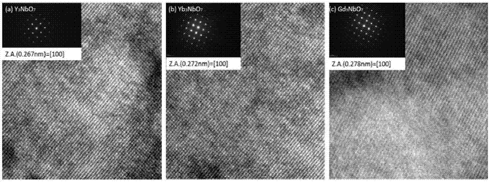
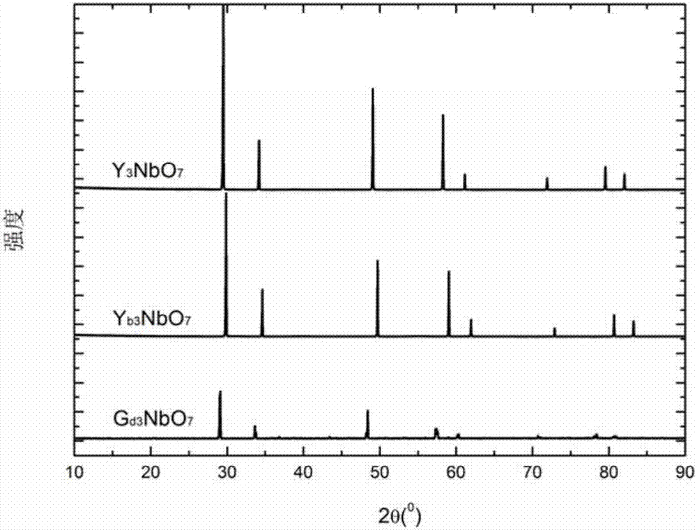
High-temperature thermal barrier coating material

A coating material, warm technology, applied in the field of materials science and engineering

Inactive Publication Date: 2017-06-23
TSINGHUA UNIV
View PDF5 Cites 20 Cited by
  • Summary
  • Abstract
  • Description
  • Claims
  • Application Information

AI Technical Summary

Problems solved by technology

[0004] Aiming at the series of problems existing in the current commercial YSZ thermal barrier coating during high-temperature use, the

Method used


Image

  • High-temperature thermal barrier coating material
  • High-temperature thermal barrier coating material
  • High-temperature thermal barrier coating material

Examples


Embodiment 1

[0026] Embodiment 1: Preparation Y 3 NbO 7 Thermal Barrier Coating Materials

[0027] Utilize the aforementioned solid-phase method to prepare Y 3 NbO 7 The powder is sprayed granulated and dried to make a high-fluidity powder with a particle size of 30-70 microns. A layer of CoCrAlY alloy with a thickness of about 250 microns is deposited on the surface of the cobalt-based superalloy by electron beam physical vapor deposition technology. The junction layer, and then deposit Y with a thickness of about 300 microns on its surface by APS method 3 NbO 7 Ceramic coating, coating system structure such as Figure 6 shown. After testing, the porosity of the coating is ~11%, the thermal conductivity of the coating is 0.48W / m·K at 1000°C, and the phase structure remains stable from room temperature to 1600°C.

Embodiment 2

[0028] Embodiment 2: Preparation of Yb 3 NbO 7 thermal barrier coating

[0029] Utilize the aforementioned solid-phase method to prepare Yb 3 NbO 7 The powder is sprayed granulated and dried to make a high-fluidity powder with a particle size of 30-70 microns. A layer of NiCrAlY alloy with a thickness of about 250 microns is deposited on the surface of the nickel-based superalloy by electron beam physical vapor deposition technology. Junction layer, and then deposit Yb with a thickness of about 300 microns on its surface by APS method 3 NbO 7 Ceramic coating, coating system structure such as Figure 7 shown. After testing, the porosity of the coating is ~10%, the thermal conductivity of the coating is 0.41W / m·K at 1000°C, and the phase structure remains stable from room temperature to 1600°C.

Embodiment 3

[0030] Embodiment 3: preparation Gd 3 NbO 7 thermal barrier coating

[0031] Gd was prepared by the aforementioned solid-phase method 3 NbO 7 The powder is sprayed granulated and dried to make a high-fluidity powder with a particle size of 30-70 microns. A layer of FeCrAlY alloy with a thickness of about 150 microns is deposited on the surface of the nickel-based superalloy by electron beam physical vapor deposition technology. The junction layer, and then deposit Gd with a thickness of about 200 microns on its surface by APS method 3 NbO 7 ceramic coating. The structure of the coating system is as Figure 8 As shown, the porosity of the coating is ~10%, the thermal conductivity of the coating is 0.46W / m·K at 1000°C, and the phase structure remains stable from room temperature to 1600°C. Embodiment 4: preparation (La 0.7 Y 0.3 ) 3 NbO 7 thermal barrier coating


PUM

PropertyMeasurementUnit
Particle sizeaaaaaaaaaa
Thermal conductivityaaaaaaaaaa

Abstract

The invention relates to a high-temperature thermal barrier coating material. The high-temperature thermal barrier coating material is rare earth niobate and a solid solution thereof. The chemical constitution of the rare earth niobate is Ln3NbO7, and Ln comprises the rare earth elements of La, Pr, Nd, Sm, Eu, Gd, Tb, Dy, Ho, Er, Tm, Yb, Lu, Y and Sc. The chemical constitution of the solid solution is Ln3(Nb1-xTax)O7 (x is larger than or equal to 0 and smaller than 1). Ln is a combination of one or more than one of the rare earth elements. The high-temperature thermal barrier coating material is characterized in that the heat conductivity of the material is low, when the temperature is 1000 DEG C, the intrinsic thermal conductivity of a compact block body is 1.1-1.4 W/m.k, compared with a commercial yttria-stabilized zirconia (YSZ) material (the thermal conductivity is about 2.5 W/m.k) with the weight percentage being 7%-8%, the thermal conductivity of the material is reduced by a large margin, and the material keeps phase stability and excellent oxygen-resistance capacity from the indoor temperature to the temperature of 1600 DEG C. The material can be applied to protection of high-temperature metal hot end parts of gas turbines or aero-engines.

Description

technical field [0001] The invention belongs to the technical field of material science and engineering, and in particular relates to a high-temperature thermal barrier coating material and its application. Background technique [0002] In order to improve the efficiency of aeroengines or gas turbines and reduce carbon emissions, the inlet temperature requirements are getting higher and higher. However, excessively high temperatures will bring more severe operating conditions to the metal parts of the thermal engine. Ordinary single crystal or superalloys have already reached the point of use. limit, it is difficult to meet the requirements. To solve this problem, thermal barrier coating technology has been widely used in recent years. Ceramic thermal barrier coatings have the functions of heat insulation, wear resistance, corrosion resistance and oxidation resistance, and are widely used in aerospace, aviation and energy fields, especially in high-pressure turbine blades, ...

Claims


Application Information

Patent Timeline
IPC IPC(8): C23C4/10C23C4/134C23C4/129C23C14/08C23C14/30
CPCC23C4/10C23C14/083C23C14/30
Inventor 潘伟万春磊杨军
Owner TSINGHUA UNIV
Why Eureka
Try Eureka