
New energy automobile power drive system and active balancing method of battery capacity thereof

A new energy vehicle, electric drive technology, used in secondary battery charging/discharging, battery/fuel cell control devices, electric vehicles, etc. The effect of simplified management and active power balance

Pending Publication Date: 2017-07-07
胡楷
View PDF10 Cites 13 Cited by
  • Summary
  • Abstract
  • Description
  • Claims
  • Application Information

AI Technical Summary

Problems solved by technology

The huge number of series series has high requirements on the battery management system (BMS), so when the number of series series is high, the BMS often adopts segmented management, the system architecture is also divided into several layers, and the number of circuit units may reach dozens , the structure is extremely complex
Under the condition of the same charge and discharge current in the series branch of the battery pack, the capacity of the internal battery cells will be unbalanced due to inconsistent parameters. If the balance cannot be effectively balanced, the battery life will be greatly reduced.
In addition, the dynamic degradation of battery cells is random, and it is difficult to solve the effective management of complex battery packs only by the active and passive balance of BMS.
All of the above greatly increase the complexity of the BMS system
From a practical point of view, when large-capacity series-parallel connections are used in groups, the life and capacity of the battery pack will be much lower than that of the single battery, which will cause a huge waste of battery
[0009] 2) The balance of the remaining power between the battery cells in the battery pack requires additional circuits and the effect is not ideal
The balance circuit of the battery pack requires an additional circuit board, and the balance control function is often included in the BMS system circuit, which greatly increases the function and circuit complexity of the BMS, increases the waste of electric energy, and the effect is not ideal
[0011] 3) Slow charging speed and reduced Coulombic efficiency
[0012] The high-voltage battery pack based on battery cells connected in series and parallel must be charged as a whole. The charger will charge the battery pack with trickle current, constant current, constant voltage, etc. according to the state of the battery pack. This charging method cannot maximize the charging speed and The charging efficiency is not optimal for the life of the battery cell
In the case of simply increasing the current value of constant current charging, due to the influence of the internal polarization effect of the battery, the Coulombic efficiency of the battery pack will drop significantly, and the maximum capacity of the battery that can be used will decrease. Therefore, the charging current value cannot be increased infinitely, and the charging speed will also decrease. Unable to reach the theoretical maximum level of battery cells
[0013] 4) The overall efficiency of the motor-driven inverter is low
In the existing scheme, the efficiency loss of only the motor-driven inverter part is more than 3%
The high switching frequency leads to the prominent EMI problem of the inverter, which requires complex filter circuits and has a very serious adverse effect on the life of the motor.
[0015] 5) Damage to a single device causes the drive inverter to fail
[0016] The main circuit of the motor-driven inverter in traditional new energy vehicles adopts a three-phase full-bridge topology. Any damage to the switching device will cause the inverter to fail and the car cannot run
[0017] 6) An additional car charger is required and the charging power is very small
Limited by the weight, space, and heat dissipation of new energy vehicles, the rated power of on-board chargers is an order of magnitude smaller than that of motor-driven inverters, resulting in very slow charging speeds and long charging times for AC charging piles.

Method used


Image

  • New energy automobile power drive system and active balancing method of battery capacity thereof
  • New energy automobile power drive system and active balancing method of battery capacity thereof
  • New energy automobile power drive system and active balancing method of battery capacity thereof

Examples


Embodiment Construction

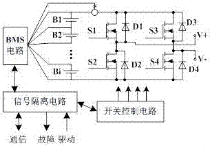
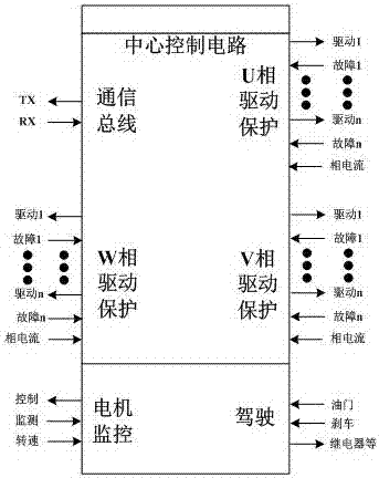
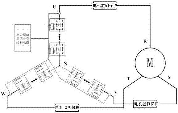
[0038] The system structure of the present invention sees figure 1 . The three module circuits are star-connected; each module circuit includes multiple modules in series; each module includes a battery pack and an inverter connected to the battery pack; the inverter is connected to the switch control circuit; all All the batteries in the battery pack are connected to the BMS circuit; the BMS circuit is connected to the switch control circuit through a signal isolation circuit; the signal isolation circuit is connected to the control center; the output ends of the three module circuits are respectively Corresponding connection with the three-phase stator winding of the motor.

[0039] The motor-driven inverter has U, V, and W three-phase bridge arms (ie, module circuits), which are connected to the R, S, and T three-phase stator windings of the driven motor. Each phase bridge arm of the inverter is composed of n identical modules in series. Take the U-phase bridge arm as an ...


PUM


Abstract

The invention discloses a new energy automobile power drive system and an active balancing method of the battery capacity thereof. The power drive system comprises three star-connected module circuits, wherein each module circuit comprises a plurality of modules which are connected in series; each module comprises a battery pack and an inverter connected with the battery pack; each inverter is connected to a switch control circuit; all batteries in each battery pack are connected with a BMS circuit; the BMS circuit is connected with a switch control circuit through a signal isolation circuit; and the signal isolation circuit is connected with a control center. Power battery packs and motor drive inverters are divided into a plurality of identical modules and then integrated into a whole, so that the BMS complexity is reduced, the service life of the battery packs is prolonged, the capacity of battery units can be actively balanced, the inverters are used as a vehicle-mounted high-power charger, the overall efficiency of the inverters is improved, redundant backup can be conveniently achieved by the consistency of the modules and the reliability of the motor drive system is improved.

Description

technical field [0001] The invention relates to a new energy vehicle power system, in particular to a new energy vehicle power drive system and a battery power active balancing method thereof. Background technique [0002] New energy vehicles can be divided into pure electric vehicles (EV) and hybrid electric vehicles (HEV), and the electric drive system provides all or part of the power for the operation of the vehicle. The electric drive system of new energy vehicles includes high-voltage components such as power battery packs, battery management systems (BMS), on-board chargers, motor-driven inverters, and motors. In addition, there are generally low-voltage electronic systems including the vehicle controller VCU / HCU, auxiliary power supply DC / DC, etc. [0003] The existing high-voltage battery pack adopts a large number of battery cells connected in series and parallel to form a group, and its output is a high DC voltage of a single port. The high-voltage battery pack...

Claims


Application Information

Patent Timeline
Patent Type & Authority Applications(China)
IPC IPC(8): B60L11/18H01M10/44
CPCB60L58/18B60L58/22H01M10/441Y02T10/72Y02T10/70Y02E60/10
Inventor 胡楷
Owner 胡楷
Learn More