System for anodic oxidation reaction and electrolyte

A technology of anodic oxidation and electrolyte, applied in the direction of material analysis, measuring devices, instruments, etc. by electromagnetic means, can solve the problem that it is difficult to obtain high-quality surfaces that meet the requirements of optical applications

Pending Publication Date: 2017-07-07
ARMY ENG UNIV OF PLA
View PDF6 Cites 1 Cited by
  • Summary
  • Abstract
  • Description
  • Claims
  • Application Information

AI Technical Summary

Problems solved by technology

It can be seen from the sintering preparation process that RB-SiC contains two phases, SiC and Si. Due to the difference in physical and chemical properties be...

Method used


Image

  • System for anodic oxidation reaction and electrolyte

Examples


Embodiment 1

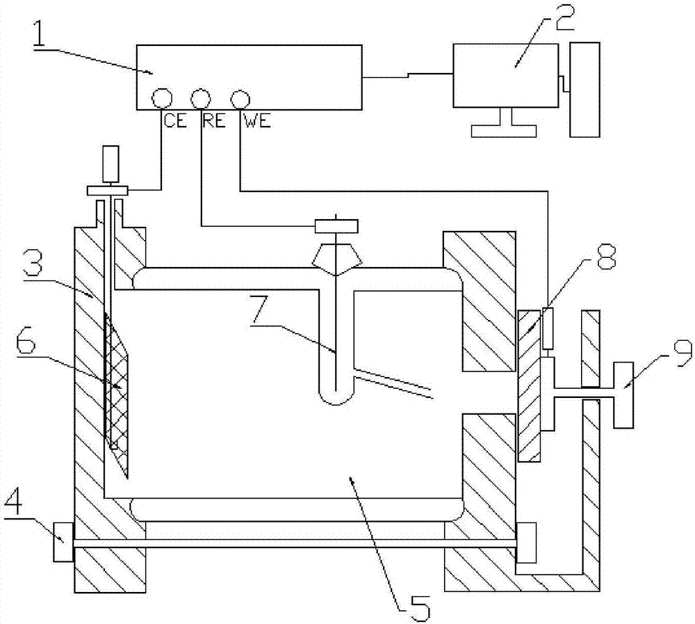
[0020] This embodiment provides a system for anodic oxidation reaction, the structure is as figure 1 As shown, the system includes a reaction vessel 3, the reaction vessel 3 is connected to a potentiostat 1, and the potentiostat 1 is connected to a computer 2; the reaction vessel 3 contains an electrolyte 5, and the electrolyte 5 is provided with a platinum grid electrode 6, and the platinum grid electrode 6 is connected to the auxiliary electrode of the potentiostat 1, the reference electrode 7 of the potentiostat 1 is immersed in the electrolyte 5, and the working electrode of the potentiostat 1 is connected to the sample 8.

[0021] A reaction vessel holder 4 is installed below the aforementioned reaction vessel 3 . The aforementioned sample 8 is installed and fixed on the side wall of the reaction vessel 3 through the sample holder 9 , and the sample 8 is in contact with the electrolyte 5 . The aforementioned reference electrode 7 adopts Ag or AgCl. The aforementioned sa...


PUM


Abstract

The invention discloses a system for anodic oxidation reaction. The system comprises a reaction container, the reaction container is connected with a constant potential rectifier, and the constant potential rectifier is connected with a computer; electrolyte is contained in the reaction container, a platinum gauze electrode is arranged in the electrolyte and is connected with an auxiliary electrode of the constant potential rectifier, a reference electrode of the constant potential rectifier is soaked in the electrolyte, and a work electrode of the constant potential rectifier is in linkage with a sample. According to the designed system, the constant potential rectifier exerts voltage between the platinum gauze cathode and the anode of the RB-SiC sample to drive hydroxide radical (OH-) in the electrolyte to move to the RB-SiC surface and oxidize the RB-SiC surface, under the driving of voltage, the hydroxide radical (OH-) penetrates through an oxidation layer and moves into RB-SiC interior to continue oxidation, and therefore the thickness of the oxidation layer is continuously increased. The reference electrode monitors the potential change of the region around the oxidation surface and converts the potential change into current data, and therefore oxidation currents in the oxidation region can be monitored in real time.

Description

technical field [0001] The invention belongs to the technical field of anodic oxidation electrolysis, and relates to a system and electrolytic solution for anodic oxidation reaction. Background technique [0002] The research on the application of silicon carbide (SiC) as an optical part began in the 1970s. Due to its high mechanical hardness, strong chemical stability, good thermal stability, high surface quality, high specific stiffness, small thermal deformation coefficient, and small thermal expansion coefficient , good dimensional stability, good optical machinability, good radiation resistance and other advantages, it has been widely used in the field of optics, especially in space optical systems, and its processing technology has become one of the research hotspots in the field of optical mirror processing. According to the preparation process, commonly used SiC materials can be divided into four types: hot press sintered SiC (HP-SiC), atmospheric pressure sintered S...

Claims


Application Information

Patent Timeline
IPC IPC(8): G01N27/416
CPCG01N27/416
Inventor 沈新民涂群章何晓晖杨小翠唐建张蕉蕉刘晴李治中张晓南王超徐磊
Owner ARMY ENG UNIV OF PLA
Why Eureka
Try Eureka