Laser processing apparatus, laser processing method and distance measurement method

A laser processing and distance technology, applied in measuring devices, laser welding equipment, metal processing equipment, etc., can solve problems such as inability to measure, measure distance errors, and inability to measure the distance between the processing point and the sound sensor.

Active Publication Date: 2017-07-14
KK TOSHIBA
View PDF8 Cites 5 Cited by
  • Summary
  • Abstract
  • Description
  • Claims
  • Application Information

AI Technical Summary

Problems solved by technology

Also, when the liquid droplets generated by the water flow adhere to the acoustic sensor, it may appear as a measurement distance error
In addition, laser range finders, stereoscopic cameras, etc. can be mentioned as general measurement techniques, but the optical path is blocked or defor

Method used


Image

  • Laser processing apparatus, laser processing method and distance measurement method
  • Laser processing apparatus, laser processing method and distance measurement method
  • Laser processing apparatus, laser processing method and distance measurement method

Examples


no. 1 approach

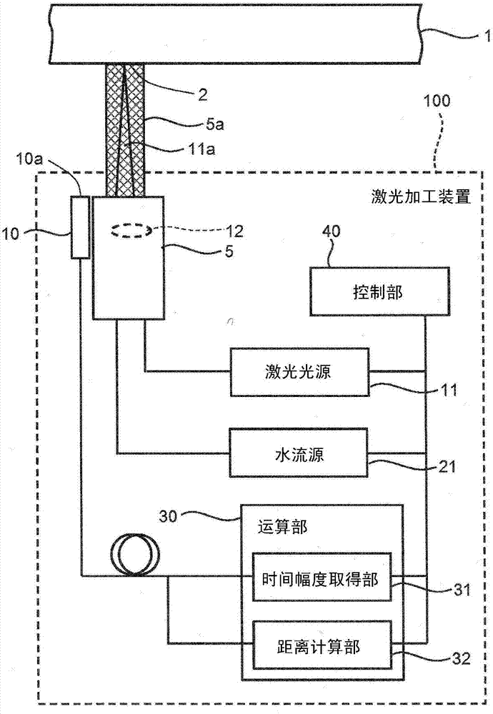
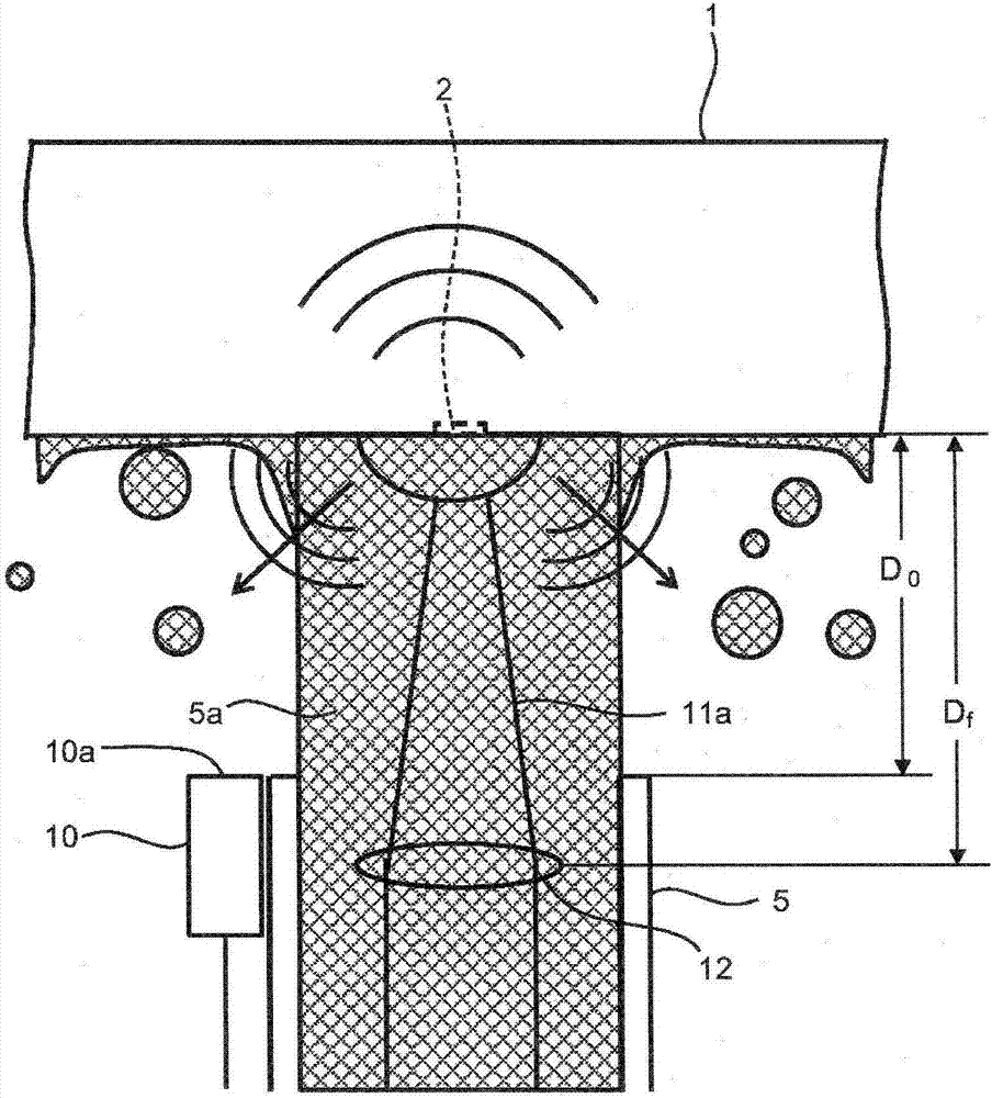
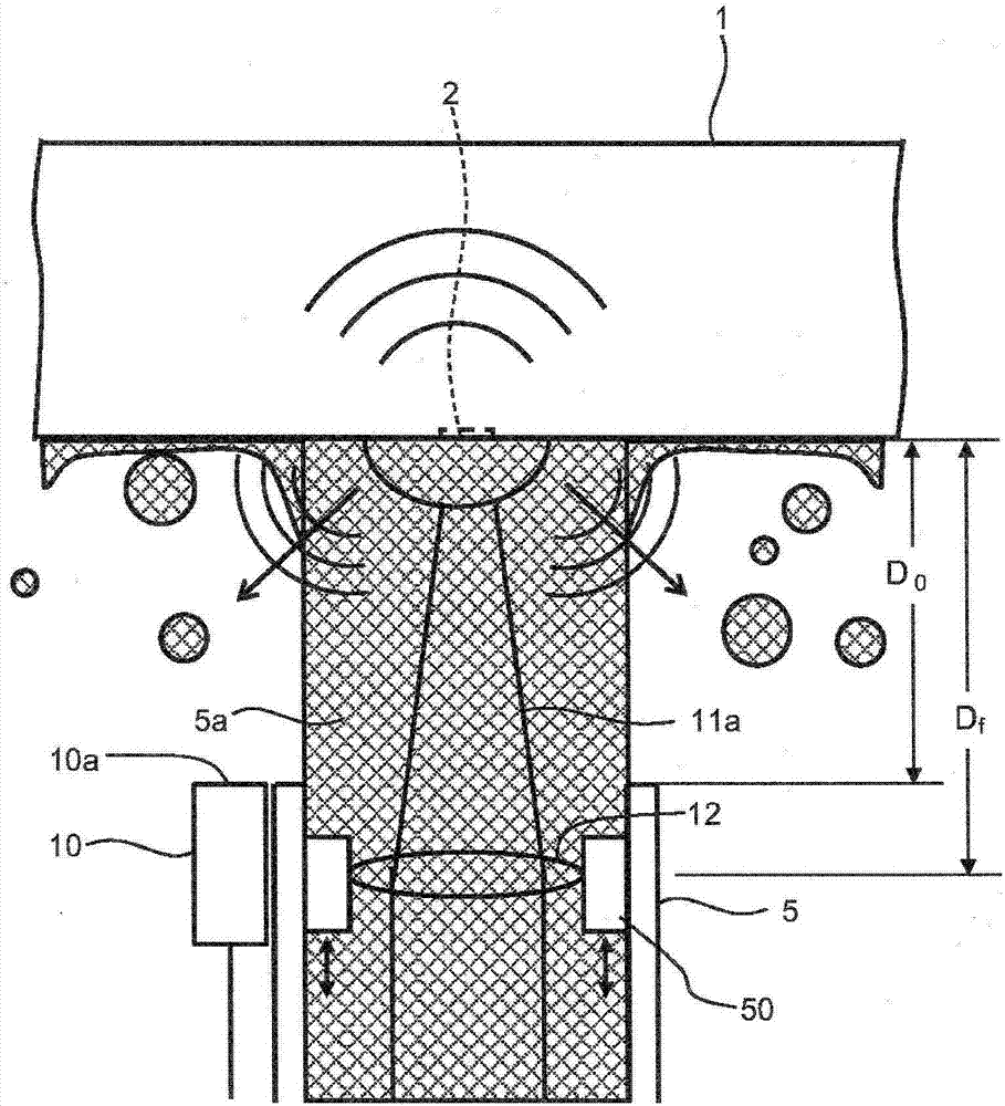
[0072] figure 1 It is a block diagram showing the structure of the laser processing apparatus of 1st Embodiment. A laser processing device (laser irradiation device) 100 irradiates a laser beam to a workpiece 1 in a gas atmosphere such as an air atmosphere to perform surface hardening treatment. Any one of a plurality of construction target sites specified on the workpiece 1 as the construction target is selected as an irradiation target site, and laser irradiation is performed respectively. The laser processing device (laser irradiation device) 100 has a laser light source 11, a water flow source 21, a water flow transmission part 5, a calculation part 30, a control part 40, an acoustic sensor 10, and a focusing distance adjustment part 50 ( image 3 ), and the mobile drive unit 90 ( Figure 4 , Figure 5 ). A focusing unit 12 for converging laser light 11 a irradiated toward the workpiece 1 is attached to the water flow transmission unit 5 .

[0073] The laser light so...

no. 2 approach

[0118] Figure 12 It is a schematic longitudinal sectional view showing the structure of the laser processing apparatus of 2nd Embodiment. This embodiment is a modification of the first embodiment. The laser processing apparatus 100 of this embodiment has a photodetector 13 .

[0119] Even when the repetition is repeated at a constant cycle, the excitation of the laser light sometimes has jitters, that is, wobbling and turbulence, on the order of several μs. By using the photodetector 13 to detect the actual light emission timing, and using the timing of the detection signal as Ti, the propagation distance D can be increased. p Then the focusing distance D f The accuracy of the measurement.

no. 3 approach

[0121] Figure 13 It is a schematic longitudinal sectional view showing the structure of the laser processing apparatus of 3rd Embodiment. This embodiment is a modification of the first embodiment. The laser processing apparatus 100 of this embodiment has two acoustic sensors 15a, 15b. In addition, the number of acoustic sensors may be three or more.

[0122] Figure 14 It is a schematic longitudinal sectional view for explaining the measurement of the construction distance. Shock waves are now emitted from the processing point 2 and reach the two sound sensors 15a, 15b. Let the distance between the processing point 2 calculated from the propagation time to the acoustic sensor 15a and the receiving portion of the acoustic sensor 15a be D1. From this it can be concluded that the machining point 2 exists on a spherical surface with a radius D1 from the receiving portion of the acoustic sensor 15a. Similarly, let the distance between the processing point 2 calculated from t...


PUM


Abstract

According to an embodiment, a laser processing apparatus (100) has: a laser light source (11); a light collector (12); a water transmitter (5); a sound sensor (10); a time-width acquirer (31); and a distance calculator (32). The laser light source (11) emits the laser light (11a). The light collector (12) collects the laser light (11a) on a workpiece (1). The water transmitter (5) supplies a water stream (5a) to a surface to be treated of the workpiece (1). The sound sensor (10) is provided at a predetermined position relative to at least one of the water transmitter (5) and the light collector (12), and receives a sound coming from the surface to be treated. The time-width acquirer (31) detects time width from a reference time point to a time point when the sound sensor (10) receives the sound. The distance calculator (32) calculates a distance from one of the water transmitter (5) and the light collector (12) to the surface to be treated.

Description

technical field [0001] Embodiments of the present invention relate to a laser processing device, a laser processing method, and a distance measuring method. Background technique [0002] In nuclear power plants and other power plants that require high safety, during periodic maintenance, automatic equipment is used to enter equipment that is difficult for humans to enter, such as furnace equipment, and various maintenance works such as inspection, surface modification, and repair are performed. Among them, as a countermeasure against SCC (Stress Corrosion Cracking) caused by the tensile stress remaining in the welded part, laser peening methods and devices capable of effectively preventing the occurrence of SCC have been developed. [0003] Figure 48 It is a schematic diagram showing the principle of laser shock peening. When the laser light 11 a with a pulse width of about several ns is condensed into a spot with a diameter of about 1 mm by the focusing unit 12 and irradi...

Claims


Application Information

Patent Timeline
IPC IPC(8): B23K26/352B23K26/14B23K26/70G01S11/14
CPCB23K26/14B23K26/356B23K26/702G01S11/14
Inventor 山本摄伊藤阳野村航大千星淳千田格椎原克典市川博也广田圭一吉田昌弘
Owner KK TOSHIBA
Why Eureka
Try Eureka