
System and method for microbial/photocoupled reduction of carbon dioxide to produce methane

A carbon dioxide and photoelectric coupling technology, applied in the field of methane production systems, can solve the problems of high cost, high degree of automation, frequent adsorption and desorption, etc., and achieve the effects of low cost, environmental protection, energy saving and emission reduction, and good application prospects

Active Publication Date: 2019-03-19
CHONGQING UNIV
View PDF6 Cites 2 Cited by
  • Summary
  • Abstract
  • Description
  • Claims
  • Application Information

AI Technical Summary

Problems solved by technology

[0003] Carbon dioxide capture methods include absorption method, adsorption method, deep burial storage method and resource utilization of carbon dioxide. 2 In terms of research, the absorption method is mainly carried out, which has a large absorption capacity and good absorption effect, but the cost is high and the separation efficiency is not high; while the adsorption method has a simple process and low energy consumption, but the adsorbent capacity is limited and the amount used is large, and Adsorption and desorption are frequent, requiring a high degree of automation; CO 2 Although the deep burial storage method can have a certain positive effect on reducing the greenhouse effect, it cannot be recycled, and it cannot completely solve the problem of the greenhouse effect.
But the system is reducing CO 2 In the process, an external power source is required, that is, input electric energy to overcome CO 2 Revert to CH 4 energy barrier, but electric energy is a high-grade secondary energy
[0005] At present, in the artificial photosynthesis system, using solar energy, microorganisms are used as catalysts to directly convert CO 2 The study of electrochemical reduction to methane has not been reported

Method used


Image

  • System and method for microbial/photocoupled reduction of carbon dioxide to produce methane
  • System and method for microbial/photocoupled reduction of carbon dioxide to produce methane
  • System and method for microbial/photocoupled reduction of carbon dioxide to produce methane

Examples


Embodiment 1

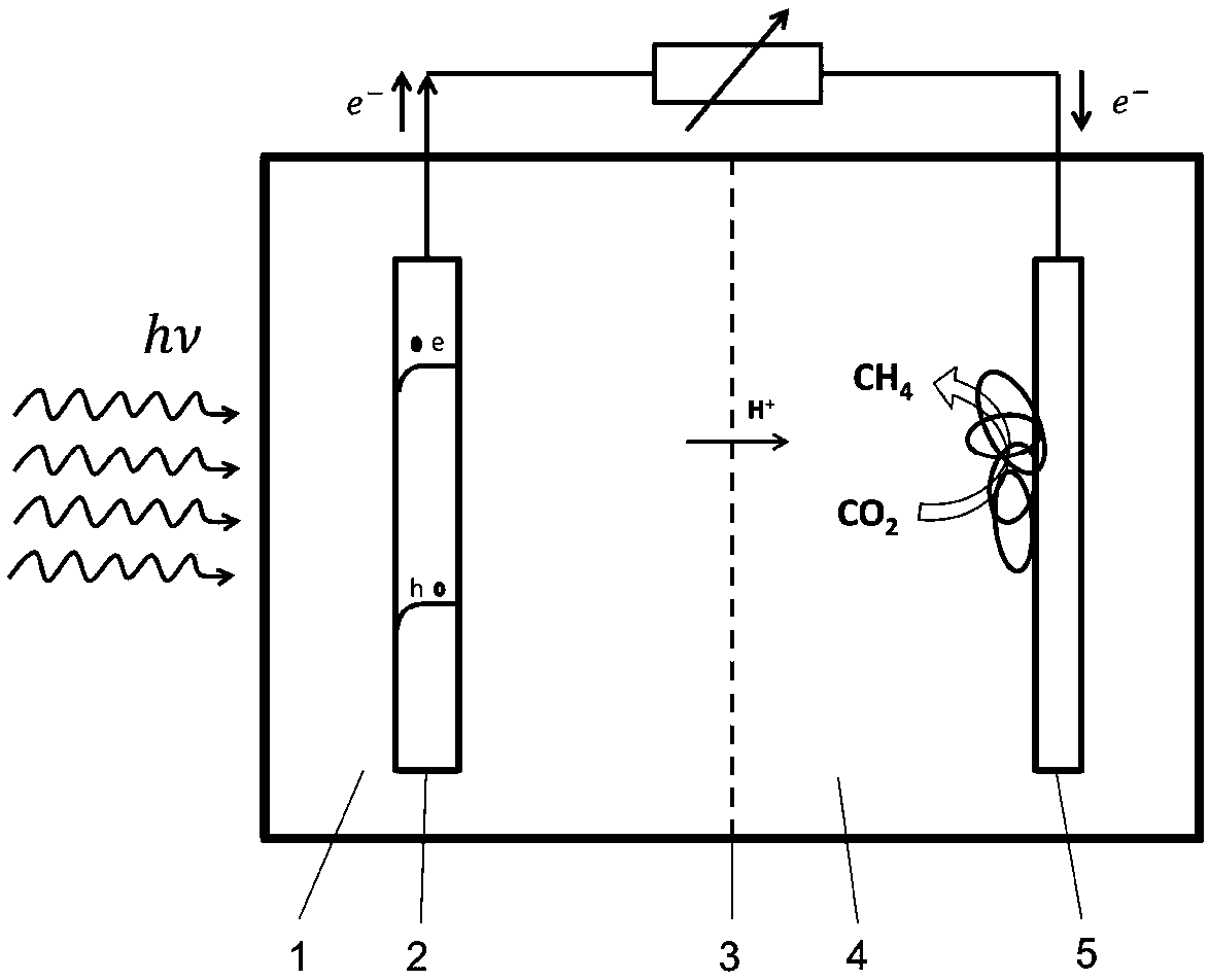
[0029] see figure 1, a microbial / photoelectric coupling reduction carbon dioxide methane production system, comprising an anode chamber 1 and a cathode chamber 4, the anode chamber 1 and the cathode chamber 4 are respectively provided with an anolyte and catholyte, between the anode chamber 1 and the cathode chamber 4 A cation exchange membrane 3 is provided, wherein: a photoanode 2 is also provided in the anode chamber 1; the photocatalyst on the photoanode 2 adopts an n-type semiconductor, and the conduction band potential of the n-type semiconductor is lower than CO 2 / CH 4 The redox equilibrium potential, meanwhile, the valence band potential of n-type semiconductor is higher than that of H 2 O / O 2 redox equilibrium potential; the cathode chamber 4 is provided with a biocathode 5, and the surface of the biocathode 5 is attached with electrochemically active methanogens; the anolyte is water or waste water containing organic matter; the catholyte is composed of inorganic...

Embodiment 2

[0032] Embodiment 2: a kind of method that microorganism / photoelectric coupling reduces carbon dioxide to produce methane, comprises the steps:

[0033] 1. Reaction system construction

[0034] The reaction system includes an anode chamber 1 and a cathode chamber 4 , and a cation exchange membrane 3 is arranged between the anode chamber 1 and the cathode chamber 4 . An anolyte and a catholyte are respectively arranged in the anode chamber 1 and the cathode chamber 4, and the anolyte is water; the catholyte is a mixed solution containing inorganic carbon source, nitrogen source, inorganic salt, buffer solution and trace elements; the catholyte is in this Adopted in the embodiment: 0.1~0.3g / LKH 2 PO 4 , 2~3g / L Na 2 HPO 4 , 1~4g / L NaHCO 3 , 0.2~0.6g / L NH 4 Cl and 0.1~0.2g / L CaCl 2 2H 2 A mixed solution of O and 5-15g / L trace elements. Among them, trace elements include: 2.0~5.0mg / L riboflavin, 2.0~5.0mg / L p-aminobenzoic acid, 1.0~3.0mg / L vitamin H, 1.0~3.0mg / L vitamin B ...

Embodiment 3

[0040] Embodiment 3 A method for microbial / photoelectric coupling reduction of carbon dioxide to produce methane, comprising the steps of:

[0041] 1. Reaction system construction

[0042] The reaction system includes an anode chamber 1 and a cathode chamber 4. An anolyte and a catholyte are respectively arranged in the anode chamber 1 and the cathode chamber 4. The anolyte contains organic waste water, specifically: 5-50g / LKOH and 2-10g / L A mixed solution of glucose; catholyte is a mixed solution containing inorganic carbon source, nitrogen source, inorganic salt, buffer solution and trace elements; a cation exchange membrane 3 is arranged between the anode chamber 1 and the cathode chamber 4.

[0043] 2. Prepare the photoanode; the photocatalyst on the photoanode 2 adopts n-type semiconductor, and the conduction band potential of the n-type semiconductor is lower than that of CO under any pH condition 2 / CH 4 The redox equilibrium potential, meanwhile, the valence band pot...


PUM


Abstract

The invention discloses a system and a method for reducing CO2 to produce methane through microorganism / photoelectric-coupling. The system herein includes an anode chamber and a cathode chamber, which are respectively filled with an anode solution and a cathode solution; a cation exchange membrane is disposed between the anode chamber and the cathode chamber. The system is also characterized in that a photo-anode is disposed in the anode chamber, wherein an n-type semiconductor serves as a photocatalyst on the photo-anode. The conduction band potential of the n-type semiconductor, under any pH value, is lower than the redox equilibrium potential of CO2 / CH4; meanwhile, the valence band potential of the n-type semiconductor is higher than the redox equilibrium potential of H2O / O2; a bio-cathode is arranged in the cathode chamber, wherein electrochemical active methanogens are adhered to the surface of the bio-cathode. The microorganisms can directly acquire electrons from the electrode to reduce CO2 and produce the methane, so that CO2 and microorganism conversion is achieved by means of solar energy. The system and the method have great application prospect.

Description

technical field [0001] The invention relates to the field of systems and methods for methane production, and in particular to a system and method for producing methane by reducing carbon dioxide with microorganisms / photoelectric coupling. Background technique [0002] Climate change has an increasing impact on the natural environment and human life, and the problems brought about by global warming are particularly obvious. Carbon dioxide is the main emission gas that causes global warming. With the rapid growth of population, the rapid development of industry and the wide application of fossil fuels, the emission of carbon dioxide is continuously increasing. Among them, the pollutant emission from coal combustion in power plants has always been the main source of carbon dioxide emission. Controlling the emission of carbon dioxide is considered It is the key measure to solve the greenhouse effect. Carbon dioxide emission reduction has become a global focus topic and researc...

Claims


Application Information

Patent Timeline
Patent Type & Authority Patents(China)
IPC IPC(8): C12M1/12C12M1/107C12P5/02C02F3/00C02F3/34
CPCC02F3/005C02F3/34C12M21/04C12M23/34C12M29/04C12P5/023Y02E50/30Y02P20/133Y02P20/59Y02W10/37
Inventor 付乾肖帅廖强李俊朱恂叶丁丁张亮
Owner CHONGQING UNIV
Learn More