Eureka AIR delivers breakthrough ideas for toughest innovation challenges, trusted by R&D personnel around the world.

Seven-degree-of-freedom water jet cutter

A water jet and cutter technology, applied in abrasive jet machine tools, used abrasive treatment devices, abrasives, etc., can solve the problems of unfavorable finishing, high price of EDM equipment, low precision, etc., and achieve low tool loss. Effect

Pending Publication Date: 2017-09-29
贵州航谷动力科技有限公司
View PDF6 Cites 2 Cited by
  • Summary
  • Abstract
  • Description
  • Claims
  • Application Information

AI Technical Summary

Problems solved by technology

There is a high-temperature sintered layer on the processing surface, which is not conducive to subsequent finishing
[0006] 3. EDM: It can realize the processing of difficult-to-machine metal materials. It has the advantages of no cutting force and convenient chip removal. It is especially suitable for small hole machining. However, when the EDM material is melted and vaporized, when the product meets the cooling medium Small particle residues will be produced. If the removal is not timely, it will affect the quality of the processed surface. In addition, the price of EDM equipment for processing complex three-dimensional curved surface structures is high, and the efficiency of EDM equipment processing is very low.
Aluminum alloys, titanium alloys, high-temperature alloys, etc. are widely used in the aviation industry, but electrochemical processing requires the participation of chemical media, which is not conducive to environmental protection, and electrochemical processing is less efficient than traditional processing
[0008] 5. Water jet processing: It has been used in the civilian field, but the water jet processing equipment commonly used in the domestic market is mostly used for civilian product processing. When cutting complex curved surface parts, due to reasons such as actuators and protective devices, there is low precision. , the disadvantage of poor stability

Method used


Image

  • Seven-degree-of-freedom water jet cutter
  • Seven-degree-of-freedom water jet cutter
  • Seven-degree-of-freedom water jet cutter

Examples


Embodiment Construction

[0032] The technical solution of the present invention is further described below, but the scope of protection is not limited to the description.

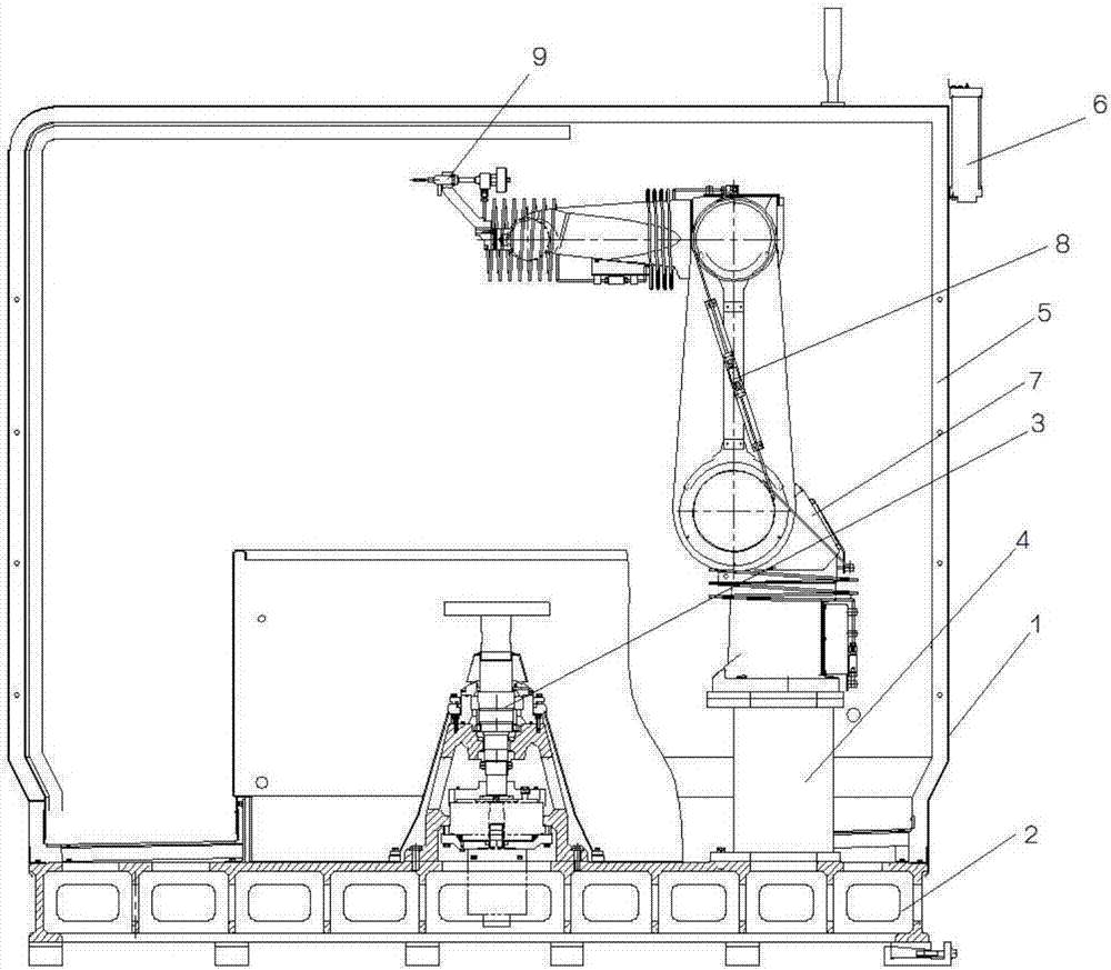
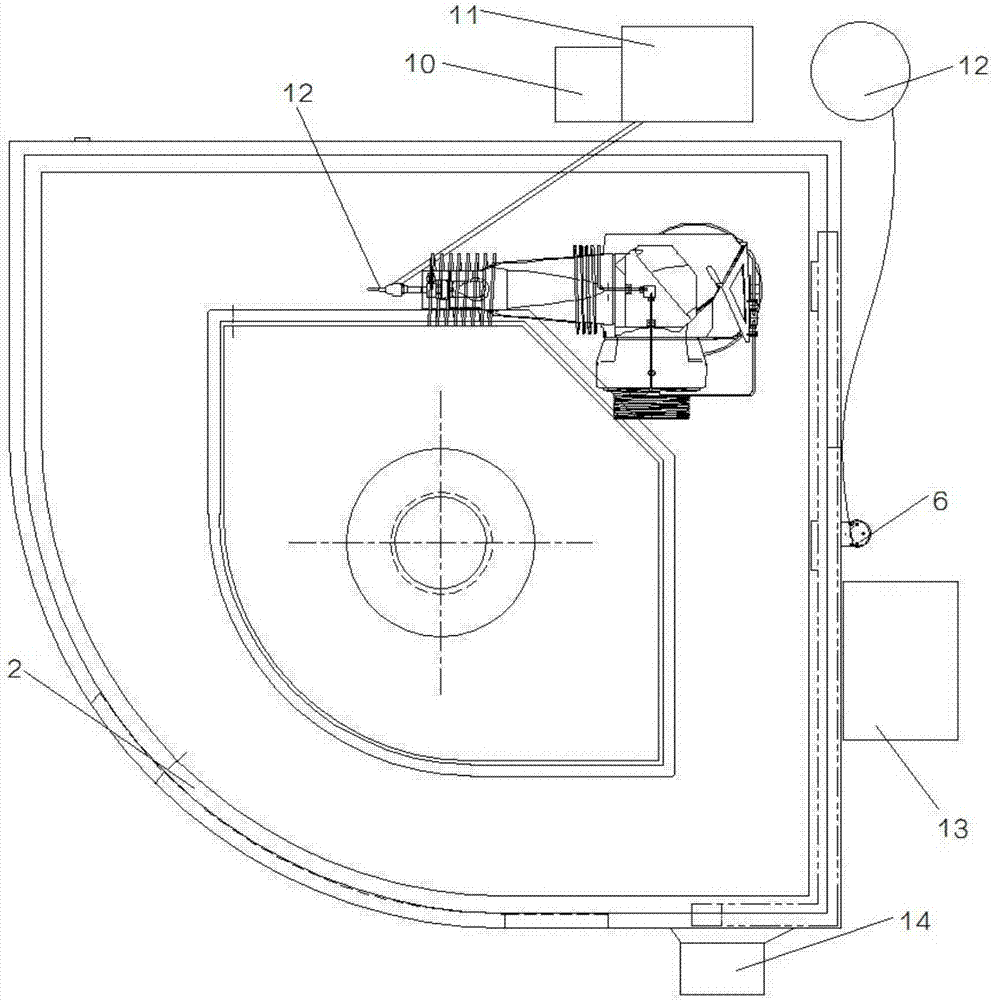
[0033] Such as figure 1 As shown, a seven-degree-of-freedom water jet cutter includes a housing 1; the bottom of the housing 1 is provided with a base 2, and the base 2 is provided with a rotating table 3 and a bracket 4 for supporting a robot 7, rotating Workbench 3, protection device 5 and other mechanisms are integral casting structures. The base 2 is integrally cast with HT300, which is the base of the entire equipment; the inner wall of the housing 1 is provided with a protection device 5, which frames the working of the device The area is used to provide protective devices for the processing area, which not only prevents the entry of foreign objects, but also prevents the splashing of water vapor and sand during processing. A small sand tank 6 is provided at the outer end of the shell 1; a robot 7 is provided on the support 4...


PUM


Abstract

The invention provides a seven-degree-of-freedom water jet cutter. The seven-degree-of-freedom water jet cutter comprises a shell, wherein a base is arranged at the bottom of the shell, and a rotary workbench and a support are arranged on the base; a protection device is arranged on the inner wall of the shell, and a small sand tank is arranged at one end of the outer side of the shell; a robot is arranged on the support; and the shell is externally connected with a cold water machine, a high-pressure pipeline device, a large sand tank, an electric part control cabinet and an operation table. According to the seven-degree-of-freedom execution mechanism, parts with complex curved surfaces can be machined; the rotary workbench is arranged, so the water jet cutter is particularly suitable for machining blade-disc parts; water jet flow and abrasive materials are mixed for cutting, so the water jet cutter is suitable for the large allowance removal of materials such as titanium alloy and high-temperature alloy which are difficult to machine; and the cutting media are the water and the abrasive sand, so that no regeneration stress and notch sintering are generated, and the machining of subsequent processes is facilitated.

Description

technical field [0001] The invention relates to a seven-degree-of-freedom water jet cutter, which belongs to the technical field of mechanical equipment. Background technique [0002] The aerospace industry uses a large number of high-strength and low-density materials, such as titanium alloys, carbon fiber composites, superalloys, etc. While these materials can provide high performance, they also bring difficulty to machining. During the processing of these parts, more than 90% of the margin needs to be removed, and the removal of large margins consumes a lot of time and material energy consumption. [0003] At present, the following methods are mostly used for the machining of titanium alloys and high-temperature alloys: [0004] 1. Cutting processing: high precision and stable processing, but high rigidity machine tool equipment requires a lot of investment, low processing efficiency and long cycle; Ti, Mo, Nb and other elements in the material make the tool easy to wea...

Claims


Application Information

Patent Timeline
Patent Type & Authority Applications(China)
IPC IPC(8): B24C3/06B24C9/00
CPCB24C3/06B24C9/006
Inventor 齐娜王叙英
Owner 贵州航谷动力科技有限公司
Why Eureka
Eureka Blog
Learn More