Method for detecting abnormality of underground heat pipe network by infrared thermography coupling soil temperature/humidity

A technology of thermal pipe network and soil temperature, applied in pipeline systems, mechanical equipment, gas/liquid distribution and storage, etc., can solve problems such as difficulty in accurately judging the location of leaks, background noise interference of detection signals, and damage to insulation layers, etc. Achieve the effect of improving fault diagnosis rate, reducing detection cost, and reducing energy waste

Inactive Publication Date: 2017-10-24
HEBEI UNIV OF TECH +1
View PDF5 Cites 8 Cited by
  • Summary
  • Abstract
  • Description
  • Claims
  • Application Information

AI Technical Summary

Problems solved by technology

[0004] The detection of direct buried heating pipe network usually adopts the manual inspection method, through direct observation and the use of "point temperature gun" to detect the surface condition of the laying surface of the heating pipe network to locate the leakage point of the heating pipe network and the damage point of the insulation layer. However, this method only It is suitable for detecting pipeline faults with large abnormality of ground surface temperature, damaged insulation layer or abnormally serious leakage, and it is difficult to realize real-time detection of faults in the entire thermal pipe network
In "Research on Fault Diagnosis Methods of Thermal Networks", Zhao Kai introduced an isolation detection method for thermal pipeline network leakage, closing the valves of some pipeline sections to isolate the corresponding pipeline sections from the entire heating network, and observing the changes in water supply and water pressure. situation, to determine whether the isolated pipe section is leaking; however, this method can only determine whether there is a leakage fault in the isolated pipe section, but cannot accurately locate the leak point
Shan Lijun introduced a sound and vibration detection method for heat pipe network leakage in "Discussion on Leakage Detection Methods of Heating Pipelines", that is, using listening sticks, leak detectors and other equipment to monitor the sound signals generated when the pipelines and fittings in the well leak. Then determine whether there is a leak, and then manually judge the distance between the leak point and the detection point; however, this method requires a high degree of experience of the staff, the detection signal is easily interfered by background noise, and it is difficult to accurately determine the location of the leak point
In "Infrared thermal imaging technology applied to thermal pipe network insulation and leakage detection technology research", Li Huizeng proposed a detection method along the direction of direct buried pipelines, using infrared thermal imaging cameras to capture surface temperature, and included surface temperature anomalies at the same time through comparative analysis Infrared thermal images of the direct-buried thermal pipeline and the normal temperature zone can be used to determine the leakage of the direct-buried thermal pipeline or the damage of the insulation layer. This method can intuitively and quickly locate the fault location of the direct-buried thermal pipeline network, but it is difficult to distinguish and judge the thermal Is the pipe network leaking or the insulation layer is damaged?

Method used


Image

  • Method for detecting abnormality of underground heat pipe network by infrared thermography coupling soil temperature/humidity
  • Method for detecting abnormality of underground heat pipe network by infrared thermography coupling soil temperature/humidity
  • Method for detecting abnormality of underground heat pipe network by infrared thermography coupling soil temperature/humidity

Examples


Embodiment 1

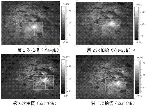
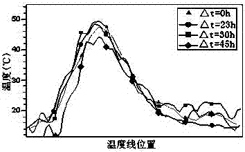
[0034] Example 1: Detection method and detection results for pipeline insulation layer damage

[0035] On January 1, 2017, infrared thermal image coupling soil temperature and humidity detection was carried out for the Gaomiao Hanhe pipeline section of Chengde City's primary heating network. The pipeline diameter is 1000mm, the buried depth is 1.5m, the water supply temperature is 110℃, and the soil is organic soil. The infrared thermal imaging lens is 3m away from the ground surface, and other parameter settings are shown in Table 1.

[0036] Table 1 Measurement parameter settings of infrared thermal imager

[0037] detection time

atmospheric temperature

ambient temperature

relative humidity

emissivity

temperature range

January 1 at 10:49

-3℃

-2℃

47%

0.95

-40℃~120℃

January 2 09:52

-7℃

-6℃

57%

0.95

-40℃~120℃

January 2 16:49

0℃

1℃

50%

0.95

-40℃~120℃

January 3rd 07:46

-8℃

...

Embodiment 2

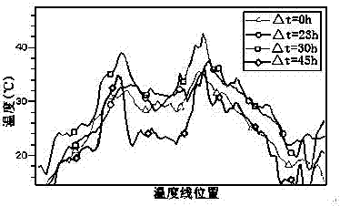
[0041] Example 2: Leak detection method and detection results of buried heat pipe network

[0042] On December 29, 2016, an infrared thermal imaging coupling soil temperature and humidity detection was carried out for the first kindergarten pipe section of the heating pipe network in Chengde City. The pipe diameter here is 100mm, the buried depth is 1.2m, and the temperature of the water supply pipe is 110°C ; Its surface is 100mm thick Dutch bricks, below the Dutch bricks is a cement mortar layer with a thickness of 100mm and a cement concrete layer with a thickness of 200mm, and then there is sandy soil below. The infrared thermal imaging lens is 3m away from the surface, and other parameter settings are shown in Table 2. .

[0043] Table 2 Infrared camera measurement parameter settings

[0044] detection time

atmospheric temperature

ambient temperature

relative humidity

emissivity

temperature range

December 29 16:19

-3℃

-1℃

41...


PUM


Abstract

The invention relates to a method for detecting the abnormality of an underground heat pipe network by infrared thermography coupling soil temperature / humidity. In the direction of an underground pipe network, the surface temperature of a direct burial heat pipe is detected; four infrared thermography images are shot; and according to the area and temperature change of a temperature abnormal region, a surface temperature abnormal region is positioned. For a region with an insulation layer damage or leakage fault, a soil temperature and humidity sensor is used for measuring and recording the soil temperature and the volume water content. Higher temperature gradient shows in the vertical direction; when the change tendency of the volume water content of the soil at the lower part of the surface temperature normal / abnormal region along with the depth is consistent, but the soil water content of the abnormal region is slightly higher than that of the normal region, it is judged that an insulation layer of the underground pipe network is damaged; and if the temperature and volume water content changes of underground soil in the two regions are prominently different along with the depth, the surface temperature abnormal phenomenon indicates the leakage of the underground pipe network. The method can accurately position the leakage point of the heat pipe and the damage point position of the insulation layer to instruct maintainers for repair, reduces blind excavation of pavements, and improves the repair efficiency.

Description

technical field [0001] The invention relates to a method for detecting the abnormality of a buried thermal pipe network by coupling the infrared thermal image with the soil temperature and humidity, specifically a method for judging the leakage of the directly buried thermal pipe network or the damage of the insulation layer by using the infrared thermal image technology coupled with the soil temperature and humidity detection method . The invention can accurately locate the leakage point of the thermal pipeline or the damaged point of the insulation layer, guide the pipeline maintenance personnel to excavate and repair the area, reduce the loss caused by blind excavation of the road surface, and improve the repair efficiency. Background technique [0002] Since the direct burial laying has the advantages of small investment, fast construction progress, less land occupation and easy coordination with other underground pipelines and facilities, the heating pipe network is oft...

Claims


Application Information

Patent Timeline
Patent Type & Authority Applications(China)
IPC IPC(8): F17D5/02F17D5/00
CPCF17D5/00F17D5/02
Inventor 刘联胜徐疆张荷韩为明纪卫王彦逍
Owner HEBEI UNIV OF TECH
Why Eureka
Try Eureka