
Laser tin welding method and device for rectifier diode assembly parts

A technology of rectifier diodes and assembly parts, applied in the field of laser applications, can solve problems such as circuit debugging, use and maintenance hidden dangers, abnormal circuit operation, low melting point of solder, etc., to avoid mechanical extrusion, energy concentration, and accurate solder joints. Effect

Active Publication Date: 2017-11-03
XIAN KING BROTHER CIRCUIT TECH
View PDF6 Cites 17 Cited by
  • Summary
  • Abstract
  • Description
  • Claims
  • Application Information

AI Technical Summary

Problems solved by technology

In addition, for electronic equipment, false welding is a common fault that causes poor contact; false welding is mainly caused by low melting point and poor strength of solder, less solder amount, stress phenomenon on the pins of the workpiece to be welded, and oxide layer or dirt on the surface The solder joints are usually in a connection state with contact resistance due to other factors, resulting in abnormal operation of the circuit and unstable phenomena that appear from time to time, which brings major hidden dangers to the debugging, use and maintenance of the circuit.

Method used


Image

  • Laser tin welding method and device for rectifier diode assembly parts
  • Laser tin welding method and device for rectifier diode assembly parts
  • Laser tin welding method and device for rectifier diode assembly parts

Examples


Embodiment Construction

[0055] Below in conjunction with accompanying drawing and specific embodiment the present invention is described in further detail;

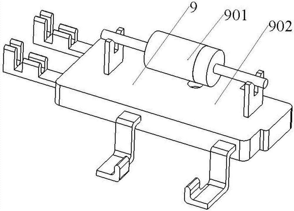
[0056] Such as figure 1 As shown, the rectifier diode assembly 9 is mainly composed of a rectifier diode 901 and a matching base 902, wherein the rectifier diode 901 is composed of lead wires on both sides (referred to as lead wires), chips, solder pieces, plastic packaging materials, etc., and its function is mainly by built-in The PN junction of the semiconductor silicon chip (grain) can conduct forward conduction and reverse cut-off characteristics for the current to achieve the purpose of rectifying the power supply; when in use, the rectifier diode 901 and the matching base 902 need to be welded together to form a rectifier diode Assemblies; the supporting base 902 is relatively independent from the rectifier diode 901, and its upper end surface is provided with two pins to weld and fix the rectifier diode 901 by soldering method, and the l...


PUM


Abstract

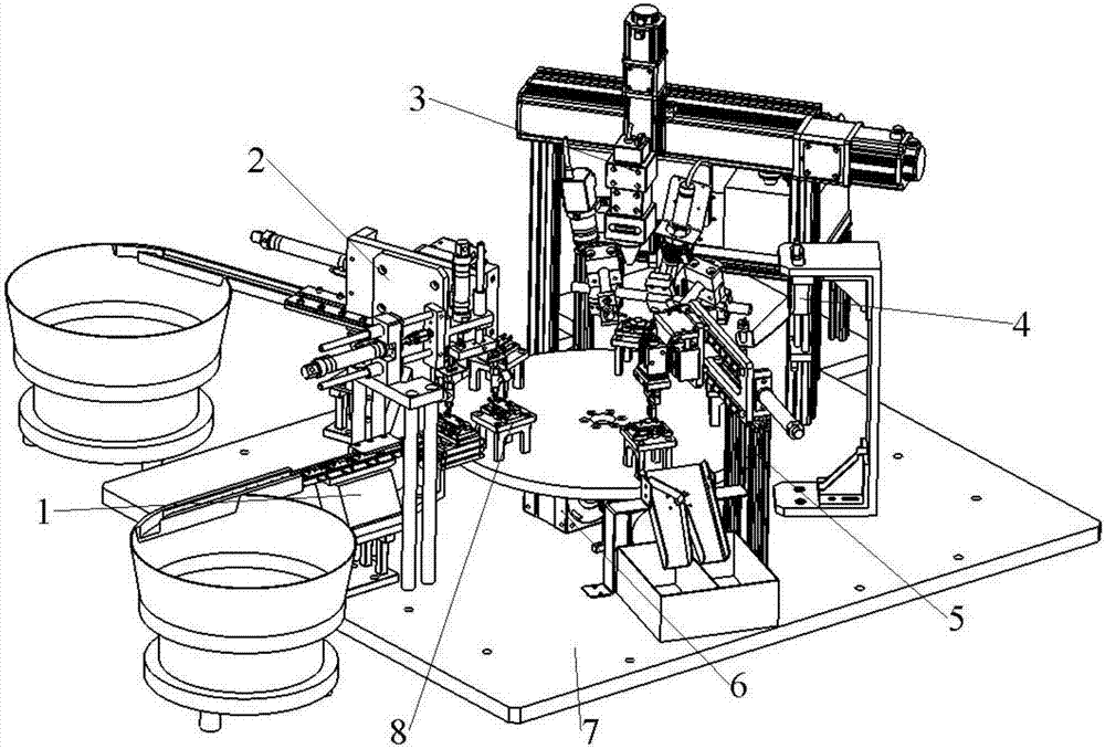
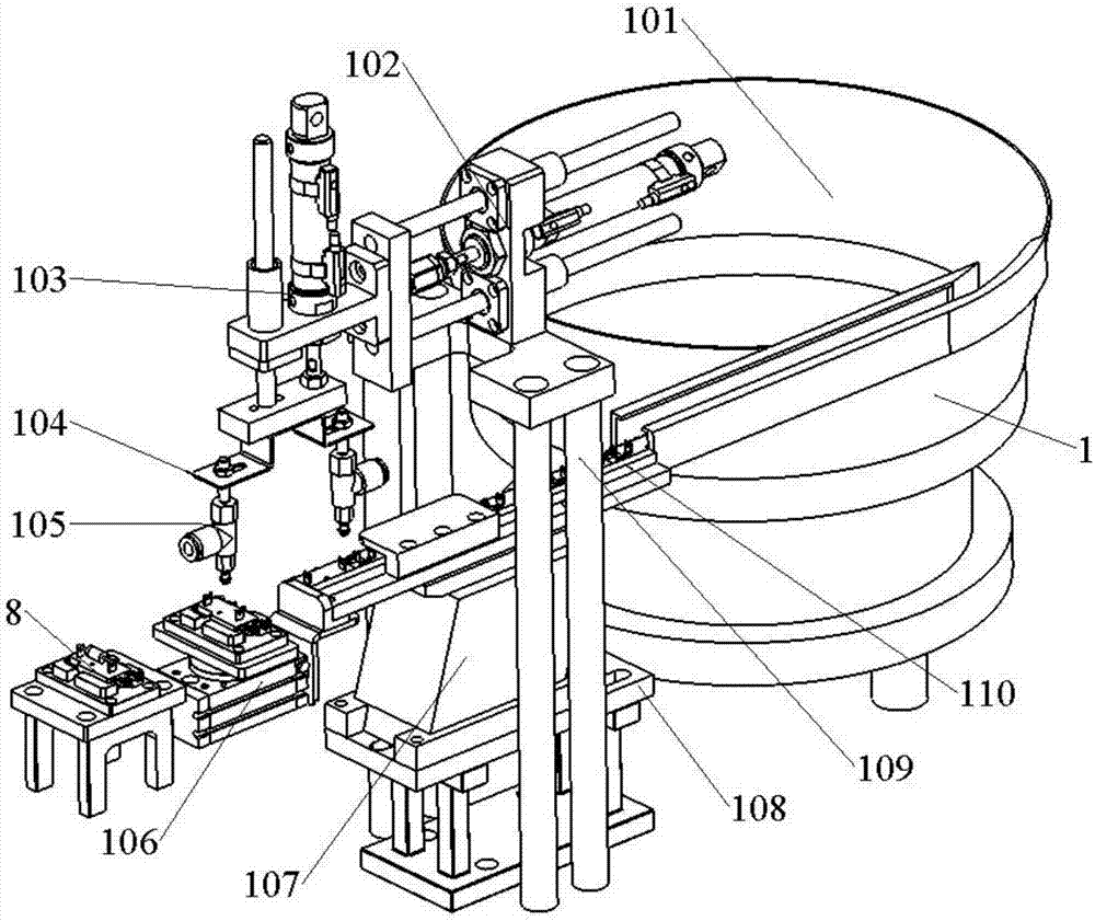
The invention provides a laser tin welding method for a rectifier diode assembly parts. The method comprises the steps of adopting a laser beam under a positive defocus status for pre-heating an area to be welded; utilizing an automatic wire feeding assembly for feeding a tin wire to a position right above the area to be welded, wherein the laser beam is acted on the tin wire through a negative defocus manner so as to quickly heat and melt the tin wire, and a melted liquid-state tin material drips on a contact surface between a rectifier diode tinning axial lead and a base pin; utilizing an ultrasonic vibrator for vibrating with fixed frequency, continuously soaking the pin and the lead at the welded part through the tin material, and forming a laser tin welding joint after cooling; and adopting the same method for welding the right side. According to the welding method, the strength and the quality of the welding joint are improved. The invention further designs an automatic laser tin welding device, which can be used for implementing the following processes such as automatic feeding and discharging, automatic laser tin welding, product quality detecting, and quality goods and inferior-quality product sorting, so that the automatic diode packaging with high efficiency, high accuracy and high quality can be realized.

Description

technical field [0001] The invention belongs to the technical field of laser applications, and in particular relates to a laser soldering method and device for a rectifier diode assembly; Background technique [0002] With the continuous update and development of information technology, human society has gradually entered the era of intelligent information, and the modern microelectronics manufacturing industry is developing in the direction of miniaturization, intelligence, high integration, high performance and diversification. Therefore, microelectronic packaging technology It will play an increasingly important role in the microelectronics manufacturing industry. [0003] At present, in the soldering process of rectifier diode assemblies, traditional electric soldering iron soldering is usually used to connect the leads of rectifier diodes to the supporting base; however, there are many limitations and disadvantages in this method: 1) Soldering with electric soldering ir...

Claims


Application Information

Patent Timeline
IPC IPC(8): B23K3/00B23K1/005B23K3/08B23K3/06B23K37/04
CPCB23K1/0056B23K3/00B23K3/063B23K3/08B23K3/087
Inventor 魏鑫磊
Owner XIAN KING BROTHER CIRCUIT TECH
Learn More