Hybrid stepping motor of installing permanent magnet on stator

A stepper motor and stepper motor technology, applied in the shape/style/structure of winding conductors, magnetic circuit shape/style/structure, electrical components, etc., can solve the difficulty of processing and installing permanent magnets and maintenance, and the inconvenience of cooling and heat dissipation of permanent magnets , motor structure and drive complexity, etc., to achieve the effect of simple manufacturing process, simplified processing and assembly process, and simplified processing and assembly process

Inactive Publication Date: 2017-11-07
SHANGHAI DIANJI UNIV
View PDF8 Cites 3 Cited by
  • Summary
  • Abstract
  • Description
  • Claims
  • Application Information

AI Technical Summary

Problems solved by technology

[0006] Patents CN201510039131.5 and CN 201520053883.2 include two inner and outer stators and a cup-shaped rotor. The columnar permanent magnet is embedded in the groove of the inner stator core. The permanent magnet is not convenient for cooling and heat dissipation. The motor winding needs to be driven by bipolar current, and the current in the winding The direction alternates periodically, the structure and drive of the motor are complex, and there are problems in processing and manufacturing; the permanent magnet of CN201020102645.3 is installed in the slot of the stator winding, and there is serious magnetic flux leakage between two adjacent tooth poles. There is the problem that the armature reaction can easily cause the leakage and demagnetization of the permanent magnet, the utilization rate of the permanent magnet is not high, and it is difficult to process the stator core, install the permanent magnet and maintain it later

Method used


Image

  • Hybrid stepping motor of installing permanent magnet on stator
  • Hybrid stepping motor of installing permanent magnet on stator
  • Hybrid stepping motor of installing permanent magnet on stator

Examples


Embodiment Construction

[0027] The following is a detailed description of the embodiments of the present invention. This embodiment is carried out based on the technical solution of the present invention, and provides detailed implementation methods and specific operation processes.

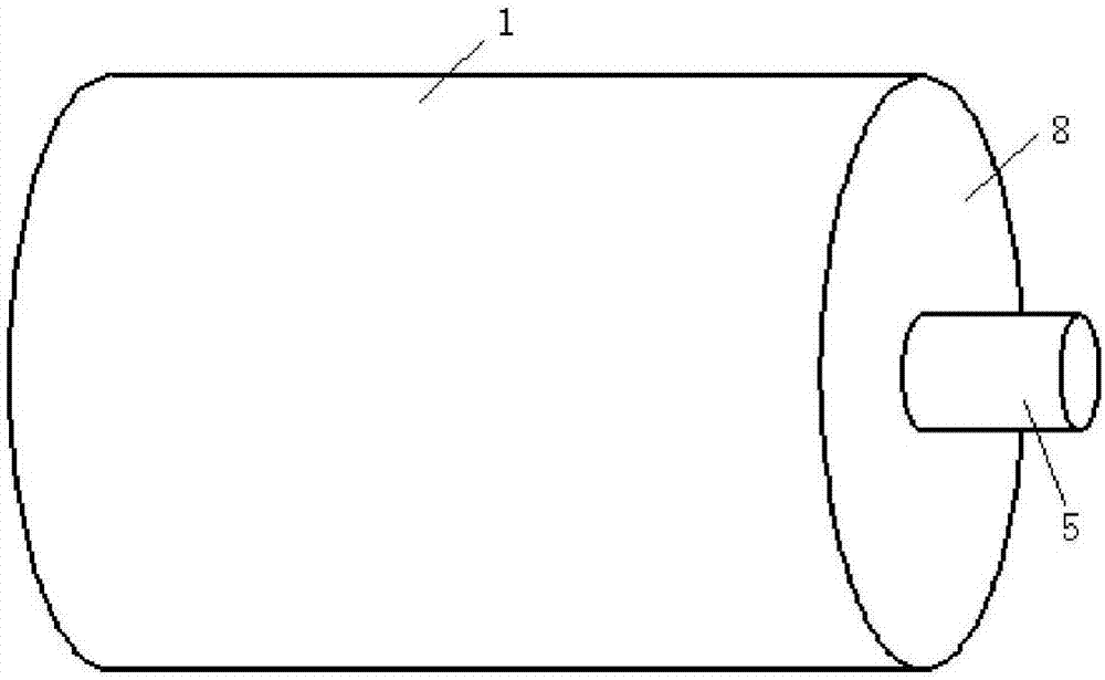
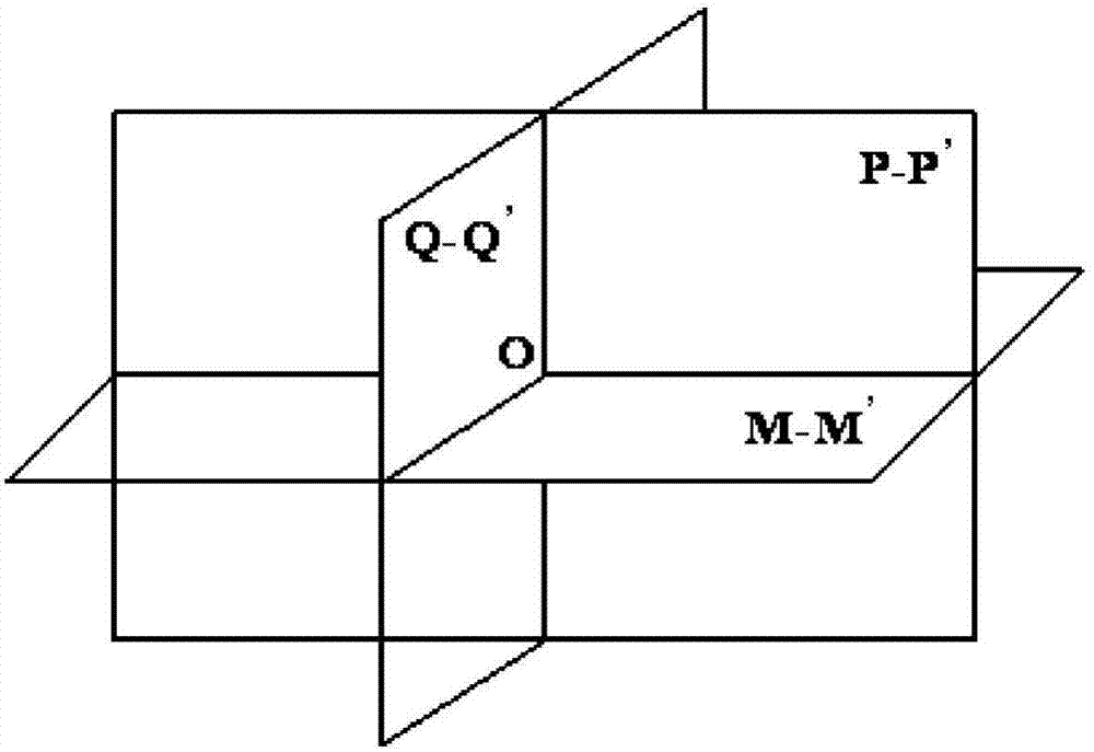
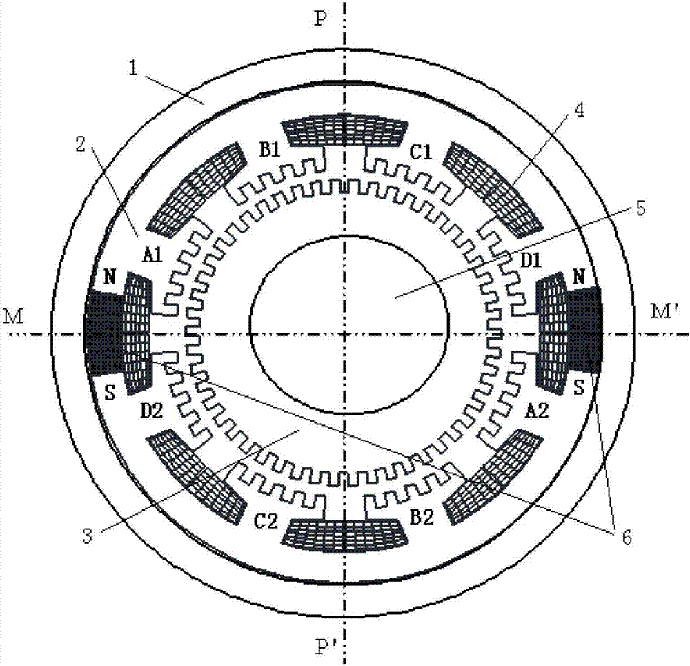
[0028] attached Figure 1~5 It is a schematic diagram of the structure of the four-phase hybrid stepper motor adopting the technical solution, figure 1 is the outline drawing of the motor, figure 2 The relationship between the planes used for the section, P-P', Q-Q', M-M' are two mutually perpendicular planes, and their common intersection point O is located at the center of the motor, and the P-P' plane and M The -M' plane is a vertical plane and a horizontal plane passing through the motor shaft respectively, and the Q-Q' plane is a plane perpendicular to the shaft. image 3 is a cross-sectional view along the Q-Q’ plane, Figure 4 is a cross-sectional view along the P-P' plane, Figure 5 It is a cross-sectional ...


PUM


Abstract

The present invention provides a hybrid stepping motor comprising a stator and a rotor. The stator comprises a chassis, a stator iron core, an armature winding, a permanent magnet and an end cover, and the rotor mainly comprises a rotor iron core and a rotating shaft. The permanent magnet is arranged at a notch at the periphery of the stator iron core, an outer circle of the permanent magnet is located at the outer circle of the stator iron core, and an inner circle is located at the groove bottom of the stator iron core. By the circumferential magnetizing, a main magnetic field in the motor is generated, and the number of the magnetic poles decides the pole number of the motor. The armature winding is arranged on the tooth poles of the stator, the windings on the radial relative tooth poles are connected in series or parallel as one phase, and the currents in the windings adopt the unipolar control. The rotor does not have the winding and the permanent magnet, the surfaces of the stator iron core and the rotor iron core facing an air gap are equipped with the small teeth of which the tooth separation distances are same. The hybrid stepping motor of the present invention enables the processing and assembly technologies of the motor and the permanent magnet to be simplified and the cost to be reduced, is reliable to operate and convenient to maintain, is high in precision and large in power density and torque density, and facilitates the development of the industries, such as the precise machine tool processing, the office automation, etc.

Description

technical field [0001] The invention relates to the field of stepping motors, in particular to a structure of a hybrid stepping motor in which a permanent magnet is installed on a stator, which is applied to the fields of computer peripheral equipment, numerical control machine tools, remote control devices and the like. Background technique [0002] There are three types of stepper motors: reactive, permanent magnet and hybrid. Reactive stepping motors have no permanent magnets, and there are small teeth on the surface of the stator and rotor cores. They have the advantages of simple structure, easy manufacturing, and high precision, but have poor efficiency, high power consumption, low torque density and low power density; permanent magnet stepping motors There are permanent magnets on the surface of the rotor, which have the advantages of small control power, high efficiency, and positioning torque when power is off, but the step angle is large, and the frequency of start...

Claims


Application Information

Patent Timeline
Patent Type & Authority Applications(China)
IPC IPC(8): H02K37/10H02K1/17H02K1/14H02K3/18
CPCH02K37/10H02K1/14H02K1/17H02K3/18
Inventor 王爱元
Owner SHANGHAI DIANJI UNIV
Why Eureka
Try Eureka